Liquid crystal display device and method for controlling same

a technology of liquid crystal display and display device, which is applied in the field of liquid crystal display device, can solve the problems of more of a decrease in crosstalk, achieve the effects of reducing image quality, reducing image quality, and reducing image quality

Inactive Publication Date: 2015-05-28
SHARP KK
View PDF6 Cites 8 Cited by
  • Summary
  • Abstract
  • Description
  • Claims
  • Application Information

AI Technical Summary

Benefits of technology

[0041]According to the first aspect of the present invention, in the liquid crystal display device, writing of a black image to the liquid crystal panel occurs during the vertical blanking period of each frame period. The vertical blanking period is a small portion of one frame period, and thus, the writing of the black image occurs over a shorter period of time compared to the writing of a normal image. The writing of the image occurs from one end to another end of the liquid crystal panel, and thus, from one end to the other end, the black insertion rate (proportion of black image display time within one frame period) becomes larger. However, the light source control unit controls the intensity of light emitted from the light sources for each group such that the intensity of light radiated to the liquid crystal panel increases from one end to the other end of the liquid crystal panel. As a result, the difference in luminance in the vertical direction (direction in which image signal lines extend) on the liquid crystal panel decreases. As a result of writing the black image, the occurrence of motion blur when displaying video or crosstalk during three-dimensional display is mitigated. Thus, a liquid crystal display device by which it is possible to mitigate a decrease in image quality when displaying video or three-dimensional images without graded luminance unevenness is realized.
[0042]According to the second aspect, a decrease in image quality resulting from crosstalk is mitigated without causing graded luminance unevenness in a liquid crystal display device that can display in three dimensions.
[0043]According to the third aspect of the present invention, the plurality of light sources constituting the backlight or sequentially turned on / off for each group. Thus, when a normal image (left eye image or right eye image) is displayed in a region corresponding to a certain group, other light sources are off. As a result, a situation in which the viewer perceives a plurality of images mixed together is mitigated. Thus, crosstalk is effectively mitigated, and it is possible to increase display quality when displaying three-dimensional images.
[0044]According to the fourth aspect of the present invention, the intensity of light emitted from the light sources is adjusted by group in accordance with the temperature surrounding the liquid crystal display device. Thus, it is possible to attain effects similar to the first aspect of the present invention while mitigating the occurrence of luminance unevenness resulting from temperature changes.
[0045]According to the fifth aspect of the present invention, in a liquid crystal display device including a temperature detection unit, it is possible to attain effects similar to the first aspect of the present invention while mitigating the occurrence of luminance unevenness resulting from temperature change.
[0046]According to the sixth aspect of the present invention, in a liquid crystal display device that obtains temperature data from an external source, it is possible to attain effects similar to the first aspect of the present invention while mitigating the occurrence of luminance unevenness resulting from temperature change.

Problems solved by technology

In liquid crystal display devices that can display in three dimensions, decreasing crosstalk is more of an issue than before.

Method used


Image

  • Liquid crystal display device and method for controlling same
  • Liquid crystal display device and method for controlling same
  • Liquid crystal display device and method for controlling same

Examples


embodiment 1

1. Embodiment 1

[0076]

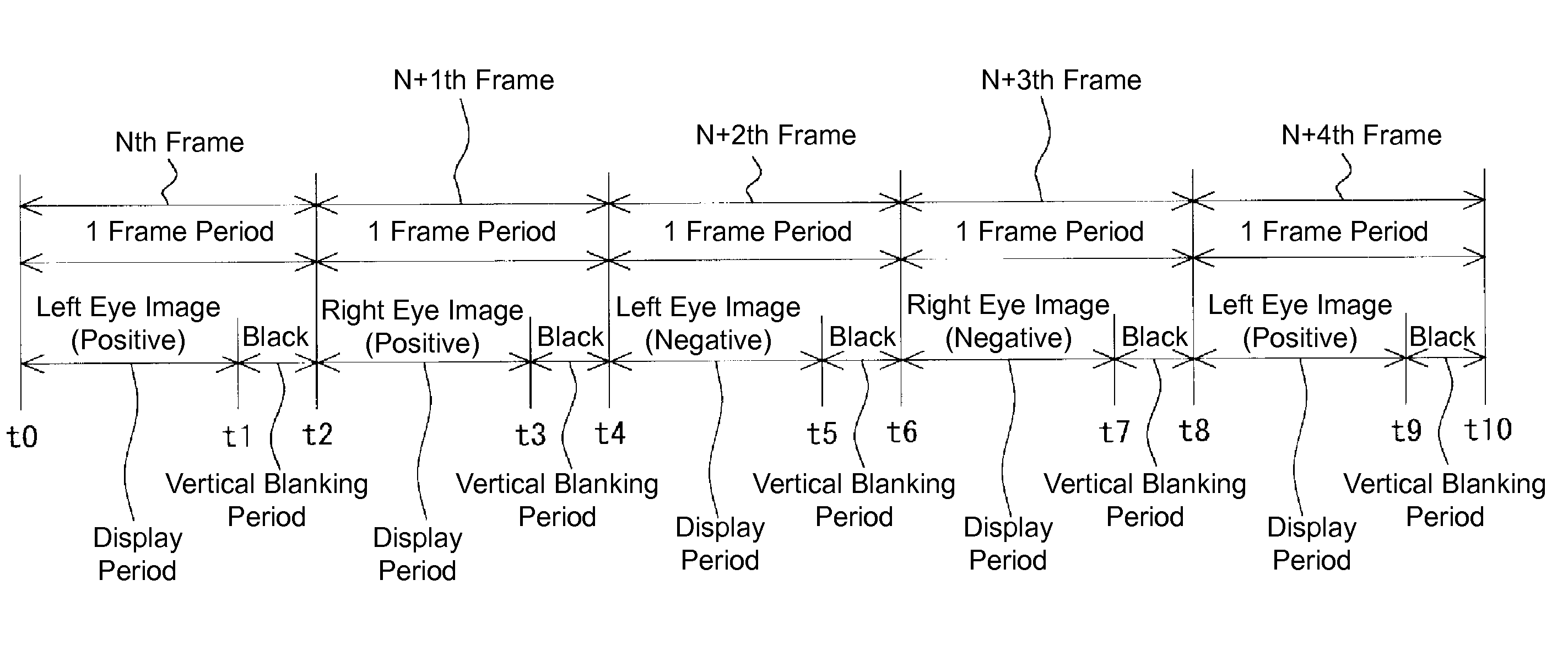
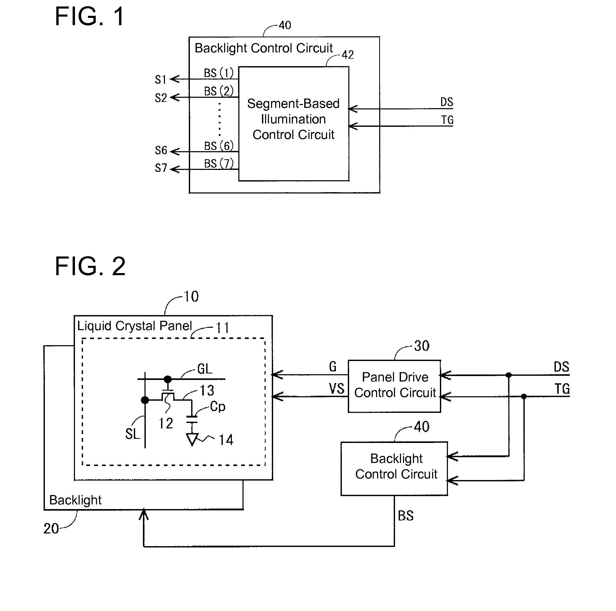
[0077]FIG. 2 is a block diagram showing an overall configuration of a liquid crystal display device of Embodiment 1 of the present invention. The liquid crystal display device includes a liquid crystal panel 10, a backlight 20, a panel drive control circuit 30 (liquid crystal panel driving unit), and a backlight control circuit 40. The liquid crystal display device is configured to be able to display in three dimensions. As a method of attaining three dimensional display, the frame sequential method in which a left eye image and a right eye image are alternately displayed is adopted. Typically, so-called double speed driving is adopted.

[0078]The liquid crystal panel 10 includes a display unit 11. The display unit 11 is provided with a plurality of image signal lines SL and a plurality of scan signal lines GL. At each intersection of image signal lines SL and scan signal lines GL, a pixel formation unit that forms pixels is provided. In other words, the display u...

modification examples

1.6 Modification Examples

1.6.1 Modification Example 1

[0098]In Embodiment 1 above, the current (drive current) for controlling the LEDs 21 was controlled to control the intensity of light emitted by the LEDs 21, but the present invention is not limited thereto. A configuration may be adopted in which the duty cycle showing the ratio of illumination periods of the LEDs 21 is determined per segment such that the LEDs 21 included in the segments S1 to S7 are switched ON and OFF based on this duty cycle, thereby controlling the intensity of light emitted by the LEDs 21. In the present modification example, as shown in FIG. 11, the duty cycle becomes gradually larger from the segment S1 to the segment S7. As a result, the intensity of light emitted by the LEDs 21 becomes gradually larger from the segment S1 to the segment S7.

modification example 2

1.6.2 Modification Example 2

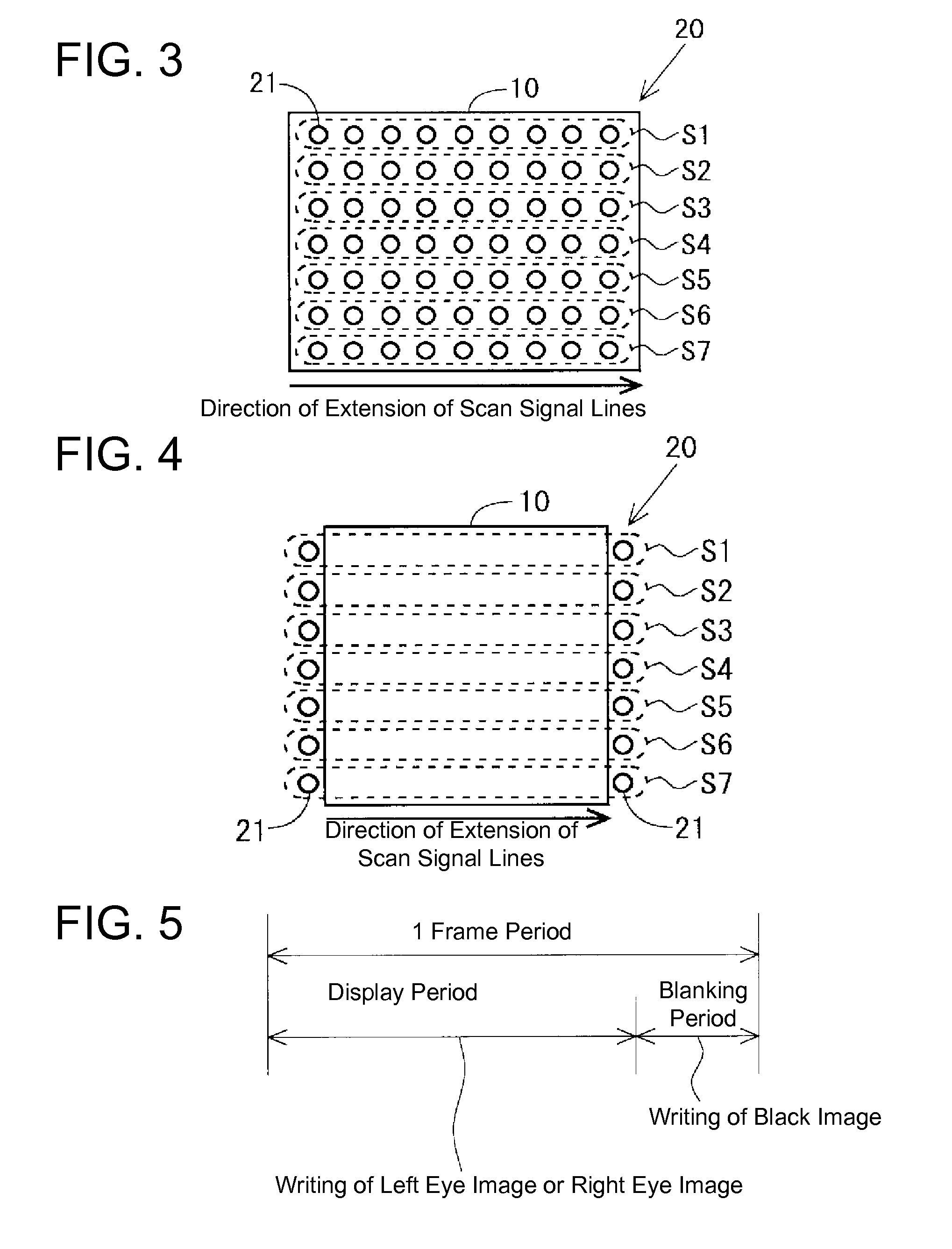
[0099]FIG. 12 is a drawing for describing the method of driving a backlight 20 of Modification Example 2 of Embodiment 1. In the present modification example, the backlight 20 is driven according to the scan driving method (LEDs 21 constituting the backlight 20 are illuminated sequentially in the vertical direction of the liquid crystal panel 10). Specifically, the LEDs 21 included in the segment S1 are illuminated during a prescribed period after image writing in a region corresponding to the segment S1 is finished, and LEDs 21 included in the segment S2 are illuminated during a prescribed period after writing in a region corresponding to the segment S2 is finished. This similarly applies to LEDs 21 included in the segments S3 to S7. In the present modification example, the segment-based illumination control circuit 42 (see FIG. 1) outputs backlight control signals BS(1) to BS(7) respectively to the segments S1 to S7 such that the LEDs 21 included in the...


PUM

PropertyMeasurementUnit
temperatureaaaaaaaaaa
temperaturesaaaaaaaaaa
luminanceaaaaaaaaaa

Abstract

Provided is a liquid crystal display device with which it is possible to suppress degradation of image quality during video display or three-dimensional display without causing gradational luminance irregularities. Writing of an image to be displayed is sequentially performed from one side of a panel to the other side thereof during each frame period, and writing of a black image is sequentially performed from the one side of the panel to the other side thereof during the vertical blanking period in each frame period. A plurality of LEDs composing a backlight are divided into a plurality of segments so that a group of LEDs arrayed in a line in the direction in which scanning signal lines extend belong to the same segment. A segment lighting control circuit in a backlight control circuit controls emission intensities of the LEDs segment by segment so that the intensity of light irradiating the panel increases gradually from the one side of the panel to the other side thereof.

Description

TECHNICAL FIELD[0001]The present invention relates to a liquid crystal display device, and more specifically, to a liquid crystal display device that performs image display while inserting a black image to mitigate a decrease in display quality.BACKGROUND ART[0002]Conventionally, as display devices, impulse type display devices such as CRTs and hold type display devices such as liquid crystal display devices are known. When focusing on individual pixels in impulse type display devices, an illumination period when images are displayed and a non-illumination period when images are not displayed occur alternately. Even when displaying videos, for example, when rewriting one frame, a non-illumination period is inserted, and thus, there are no residual images of moving objects perceived by the human viewer. Thus, the background and object can be distinguished and a video with a natural appearance can be viewed. On the other hand, in liquid crystal display devices, which are display devic...

Claims


Application Information

Patent Timeline
Patent Type & Authority Applications(United States)
IPC IPC(8): G09G3/36H04N13/00G02F1/1335
CPCG09G3/3607G02F1/133603H04N13/0025H04N13/0486G09G2320/0233G09G2320/0209G02F2001/133612G09G3/34G09G3/36H04N13/341H04N13/398H04N13/133H04N13/315G02F1/133612
Inventor IRIE, KENTAROHKAWABATA, MASAEMATSUMOTO, SHINJI
Owner SHARP KK
Why Eureka
Try Eureka