Discharge circuits of discharge paths for electromagnetic interference filters
- Summary
- Abstract
- Description
- Claims
- Application Information
AI Technical Summary
Benefits of technology
Problems solved by technology
Method used
Image
Examples
Embodiment Construction
[0026]The following description is of the best-contemplated mode of carrying out the invention. This description is made for the purpose of illustrating the general principles of the invention and should not be taken in a limiting sense. The scope of the invention is best determined by reference to the appended claims.
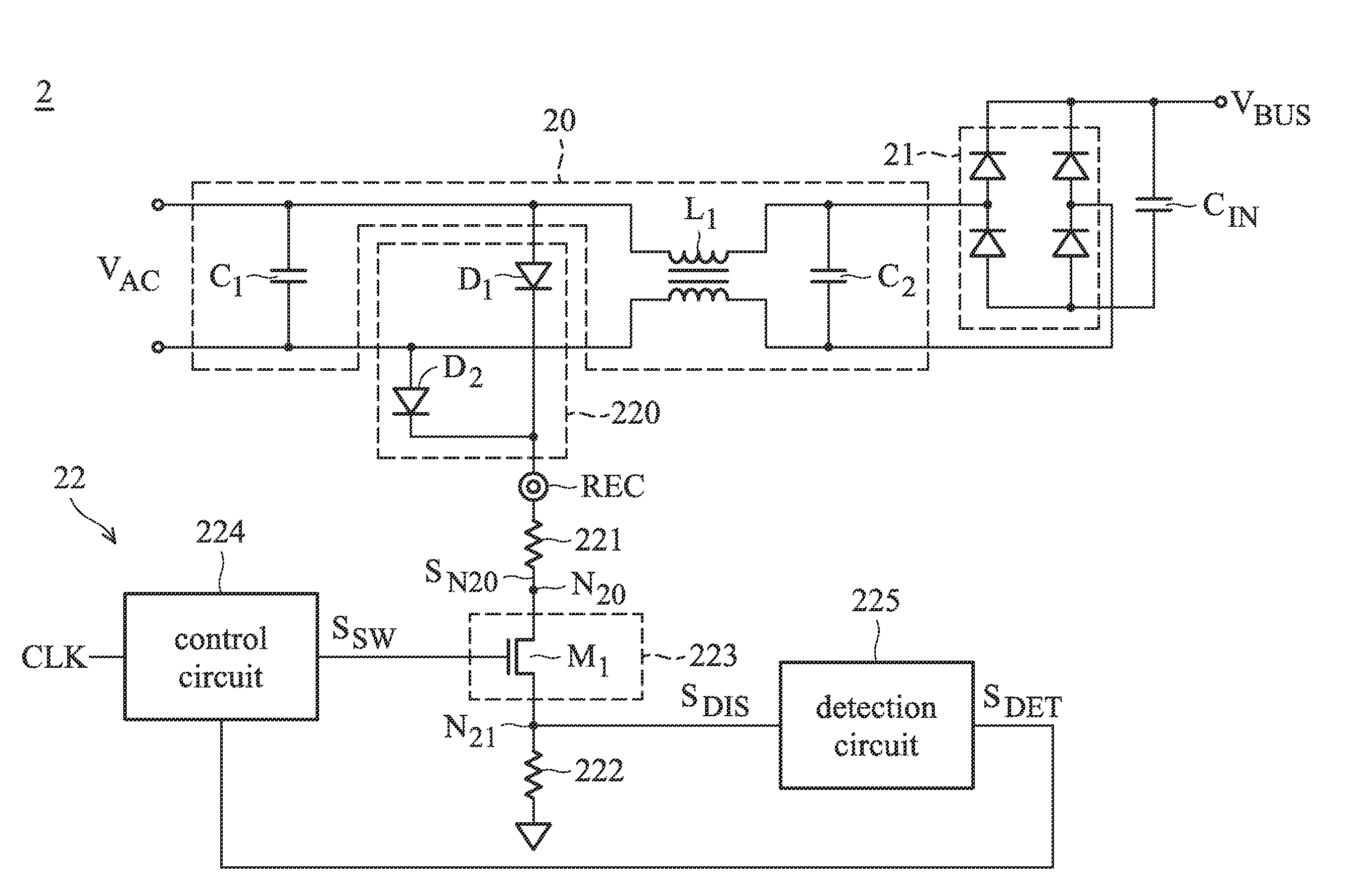
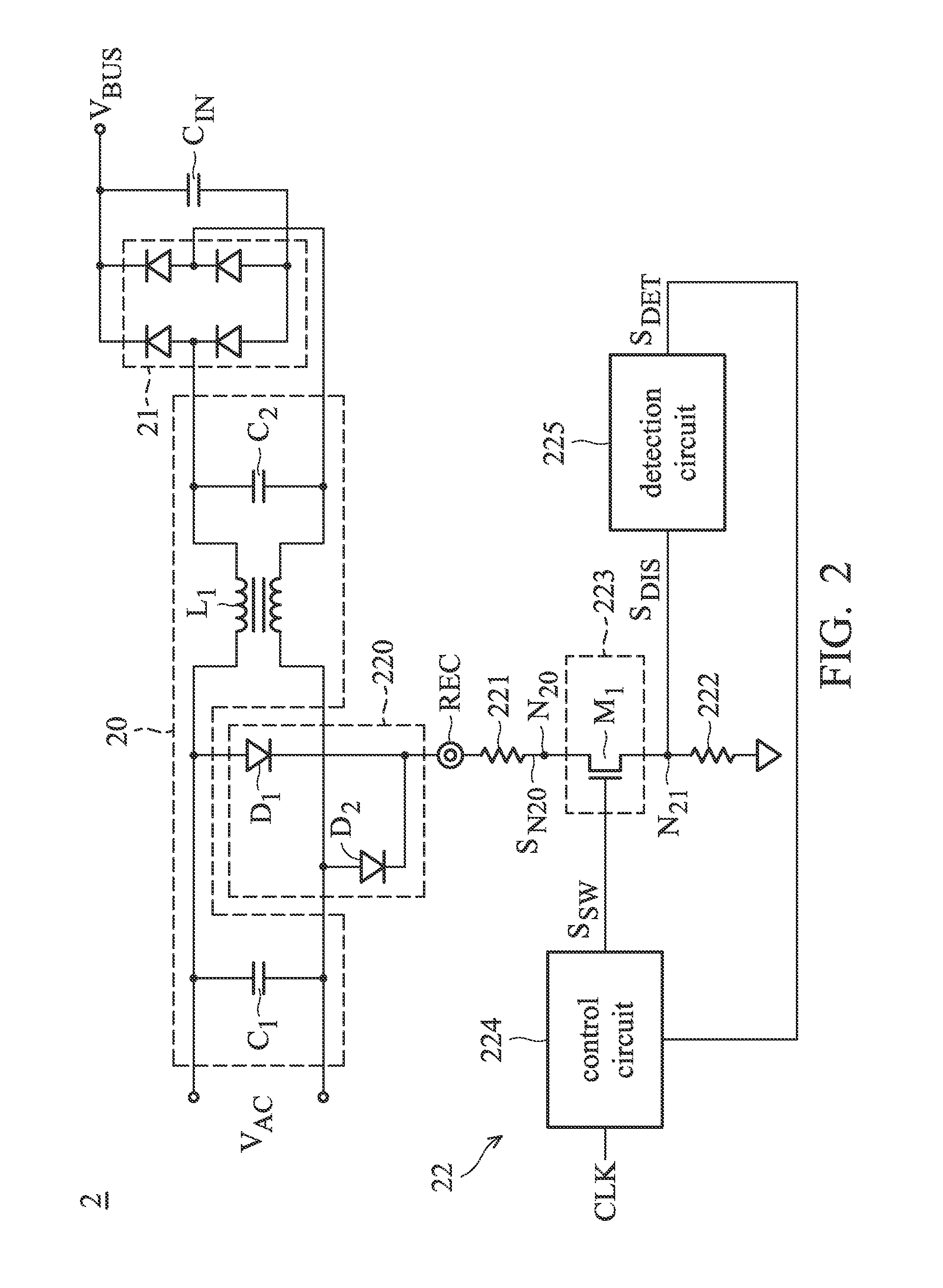
[0027]FIG. 2 shows an exemplary embodiment of a power supply circuit according to the present invention. As shown in FIG. 2, a power supply circuit 2 comprises an electromagnetic interference (EMI) filter 20, a bridge rectifier 21, a bulk capacitor CIN, and a discharge circuit 22. The EMI filter 20 is coupled between a power source VAC and a bridge rectifier 21. The EMI filter 20 comprises a choke L1, X-capacitors C1 and C2. The X-capacitor C1 is coupled across the power source VAC. The choke L1 is coupled between the power source VAC and the bridge rectifier 21. The X-capacitor C2 is coupled between the choke L1 and an input of the bridge rectifier 21. A bulk capacito...
PUM
 Abstract
Description
Claims
Application Information
 - R&D
- Intellectual Property
- Life Sciences
- Materials
- Tech Scout
- Unparalleled Data Quality
- Higher Quality Content
- 60% Fewer Hallucinations
Browse by: Latest US Patents, China's latest patents, Technical Efficacy Thesaurus, Application Domain, Technology Topic, Popular Technical Reports.
© 2025 PatSnap. All rights reserved.Legal|Privacy policy|Modern Slavery Act Transparency Statement|Sitemap|About US| Contact US: help@patsnap.com


