Lighting device having a remote wavelength converting layer

a technology of wavelength conversion layer and light source, which is applied in the direction of light source semiconductor devices, lighting and heating apparatus, coatings, etc., can solve the problems of non-uniform color distribution of light emitted from the exit surface, i.e. the surface of the remote phosphor layer from which light is emitted, and achieve the effect of reducing optical contact, optical contact, and uniform illuminance of the wavelength conversion layer

Active Publication Date: 2015-05-28
KONINKLIJKE PHILIPS ELECTRONICS NV
View PDF1 Cites 12 Cited by
  • Summary
  • Abstract
  • Description
  • Claims
  • Application Information

AI Technical Summary

Benefits of technology

[0028]According to an embodiment of the present invention, a gap, such as an air gap, is defined between the wavelength converting layer and the envelope, whereby the wavelength converting layer and the envelope may be physically separated for disabling optical contact there between. Hence, the outer surface of the wavelength converting layer and the inner surface of the envelope may be physically separated for providing an air gap or a gap with any gas or vacuum. Alternatively, or as a complement, the surface of the wavelength converting layer facing the envelope may have an uneven surface structure, such as being rough, thereby reducing the optical contact between the wavelength converting layer and the envelope even if they about each other. In the present disclosure, the term “optical contact” means the physical contact between two optical bodies having similar refractive indices implying just a slight, i.e. negligible, or no refraction of light traveling across the boundary between the two optical bodies. The optical contact between the wavelength converting layer and the envelope may preferably be reduced, or even

Problems solved by technology

A problem with remote phosphor layers is that the color distribution of light emitted from the exit s

Method used


Image

  • Lighting device having a remote wavelength converting layer
  • Lighting device having a remote wavelength converting layer
  • Lighting device having a remote wavelength converting layer

Examples


Embodiment Construction

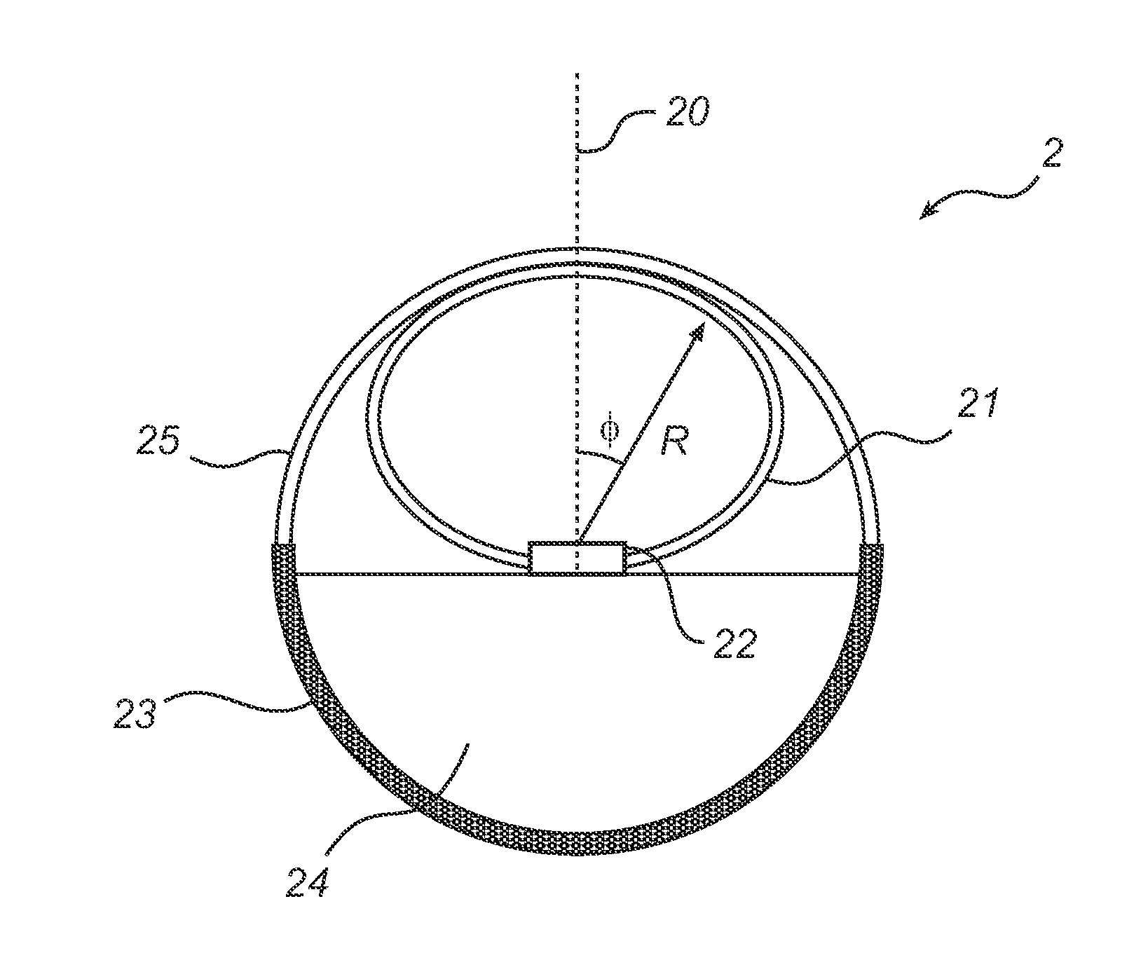
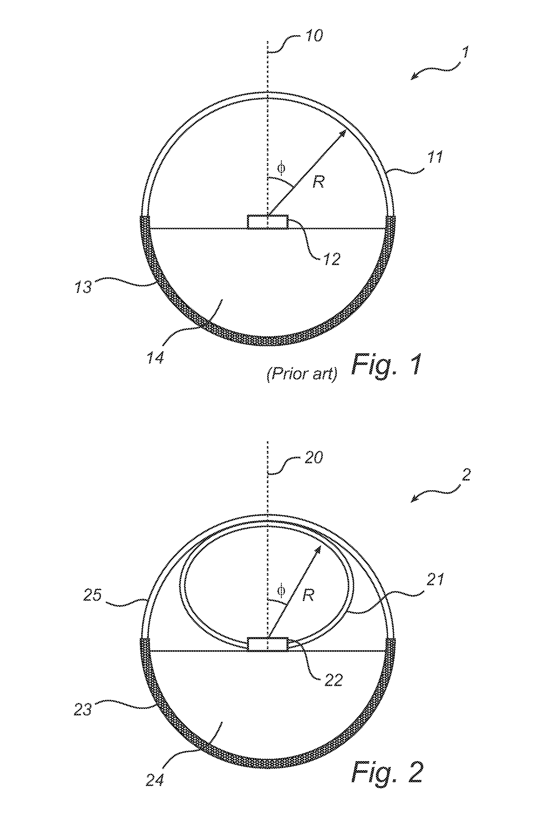
[0037]With reference to FIG. 1, a lighting device according to prior art will be described. FIG. 1 is a cross sectional view taken along a plane perpendicular to the longitudinal direction of a linear-type lighting device 1. The lighting device 1 comprises a blue LED 12, i.e. an LED emitting blue light, a heat sink 13 with a cavity 14 for driving electronics (not shown) and a wavelength converting layer 11, which also functions as an envelope enclosing the LED 12. The wavelength converting layer 11 comprises wavelength converting material, such as yellow phosphor, i.e. a phosphor emitting yellow light upon absorption of photons, preferably from the blue light of the LED 12, for providing a certain color of the light output from the lighting device 1. The distance from the LED 12 to the wavelength converting layer 11 is denoted R and the angle with respect to the optical axis 10 of the LED 12 is denoted φ. The cross section of the wavelength converting layer 11 is semi-circular and t...


PUM

PropertyMeasurementUnit
Fractionaaaaaaaaaa
Lengthaaaaaaaaaa
Surface structureaaaaaaaaaa

Abstract

According to an aspect of the present invention, a lighting device (2) is provided. The lighting device (2) comprises a wavelength converting layer (21) having a curved shape and a light source (22) arranged to emit light towards the wavelength converting layer (21). The wavelength converting layer (21) intersects a plane extending through the light source (22) and being parallel with the optical axis of the light source (22), at a curve given, in a polar coordinate system centered at the light source (22), by the equation: R(φ)=k·I(φ)1/2±D, wherein k is a constant, 0 is an angle with respect to said optical axis, /(φ) is a function defining a luminous intensity profile of the light source and D is a deviation ranging from zero to 20% of the maximum value of said curve, Rmax. The present invention is advantageous in that the lighting device (2) has a more uniform color distribution of emitted light across the wavelength converting layer (21) and the risk of color gradients and artifacts is reduced.

Description

FIELD OF THE INVENTION[0001]The present invention generally relates to the field of lighting devices having remote wavelength converting layers.BACKGROUND OF THE INVENTION[0002]Wavelength converting materials, such as phosphors, are used for tuning the color of light emitting diode (LED) based light sources. Phosphors in combination with blue LEDs are used to produce white light. Depending on the type of phosphors and the amount of conversion, the color can be tuned to achieve a desired color such as cool white or warm white. The white light is produced by a combination of transmitted (unconverted) blue light and converted, often yellowish, light.[0003]When the phosphor is arranged in a substrate or layer separate, i.e. at a certain distance, from the LED, it is referred to as a remote phosphor layer. Such a remote phosphor layer may be provided directly in an outer envelope of the lighting device or as a separate layer inside the envelope. Examples of such lighting devices are show...

Claims


Application Information

Patent Timeline
IPC IPC(8): F21K99/00
CPCF21K9/56F21V3/02F21V3/04F21S4/28F21K9/64F21Y2103/10F21Y2115/10F21V3/08F21V3/10F21V9/45F21V13/14F21V29/70
Inventor BOONEKAMP, ERIK PAULTSOI, SHUFENDUIJMELINK, ANDREAS ALOYSIUS HENRICUSVAN DREUMEL, GERARDUS WILHELMUS GERBE
Owner KONINKLIJKE PHILIPS ELECTRONICS NV
Why Eureka
Try Eureka