Watch chamber for a motor vehicle

Active Publication Date: 2015-06-04
WEIDPLAS
View PDF7 Cites 15 Cited by
  • Summary
  • Abstract
  • Description
  • Claims
  • Application Information

AI Technical Summary

Benefits of technology

The present invention is about reducing energy consumption in controlling the temperature of the passenger compartment of a motor vehicle. This is accomplished by using a water box as a heat exchanger, where exhaust air from the passenger compartment or engine compartment can be used to pre-adjust the temperature of the fresh air drawn in. This design requires less installation space in the motor vehicle and allows for compact joint accommodation of a component for removing water from the fresh air and a component for transferring the thermal energy from the exhaust air to the fresh air. The heat exchange element in the water box has good thermal conductivity and can be produced from materials such as metal or plastic. The method involves directing exhaust air towards the heat exchange element and using a conduit for directing water arising in the air conditioning unit towards the heat exchange element. The water is first mixed with exhaust air and then directed together with the exhaust air towards the heat exchange element. This design leads to additional cooling of the heat exchange element and the fresh air flowing into the water box, resulting in energy savings in the air conditioning unit.

Problems solved by technology

However, adjustment of the temperature, i.e. heating or cooling, of the air drawn in to a desired temperature in the air conditioning unit requires a significant quantity of energy.
This can significantly impair the overall energy balance of such motor vehicles.
In this method, however, the moisture content of the air drawn in is necessarily increased.
Admittedly, this method reduces the energy required to cool the fresh air.
However, the energy required to heat the fresh air drawn in, especially in winter, remains unaffected thereby.

Method used


Image

  • Watch chamber for a motor vehicle
  • Watch chamber for a motor vehicle
  • Watch chamber for a motor vehicle

Examples


Embodiment Construction

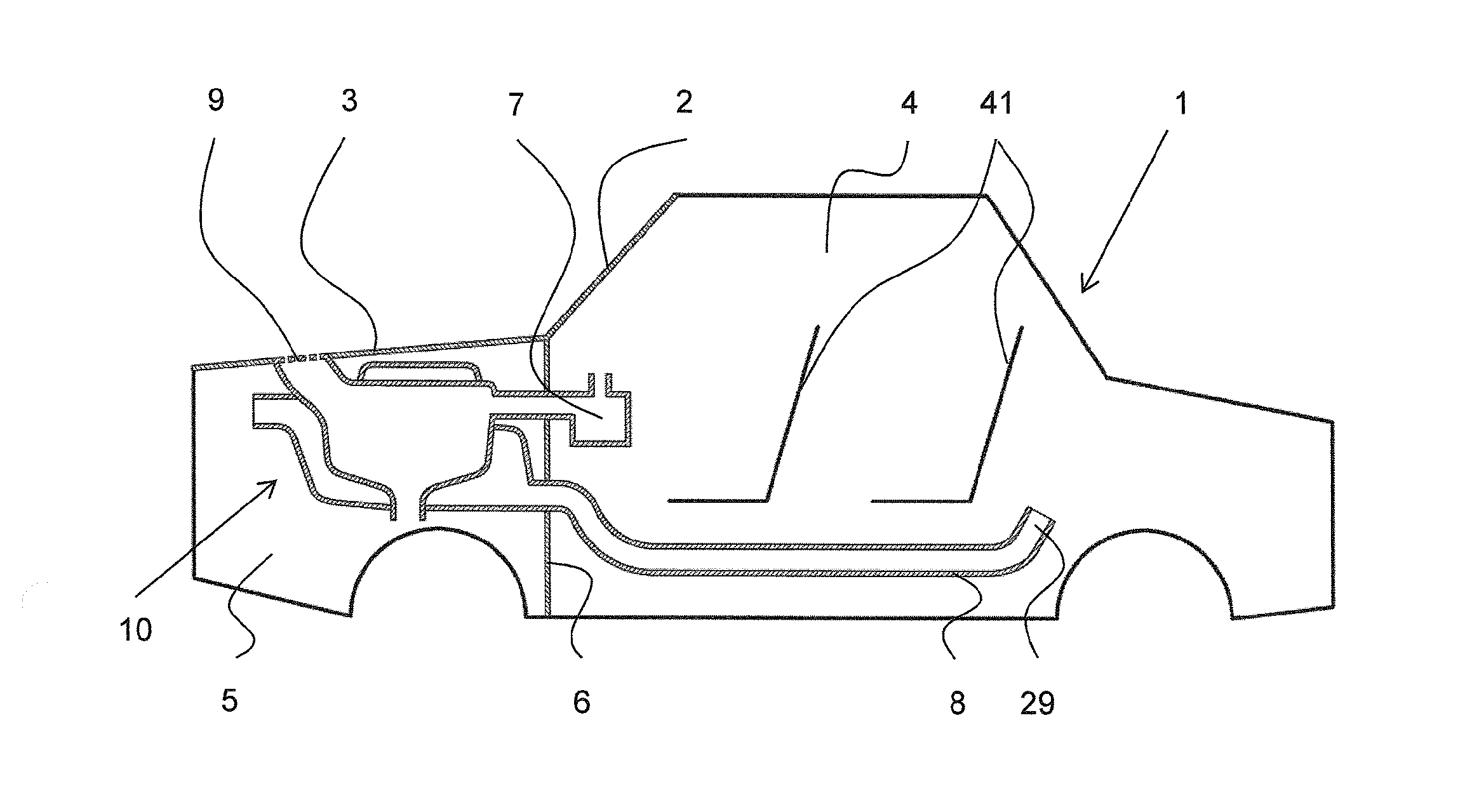
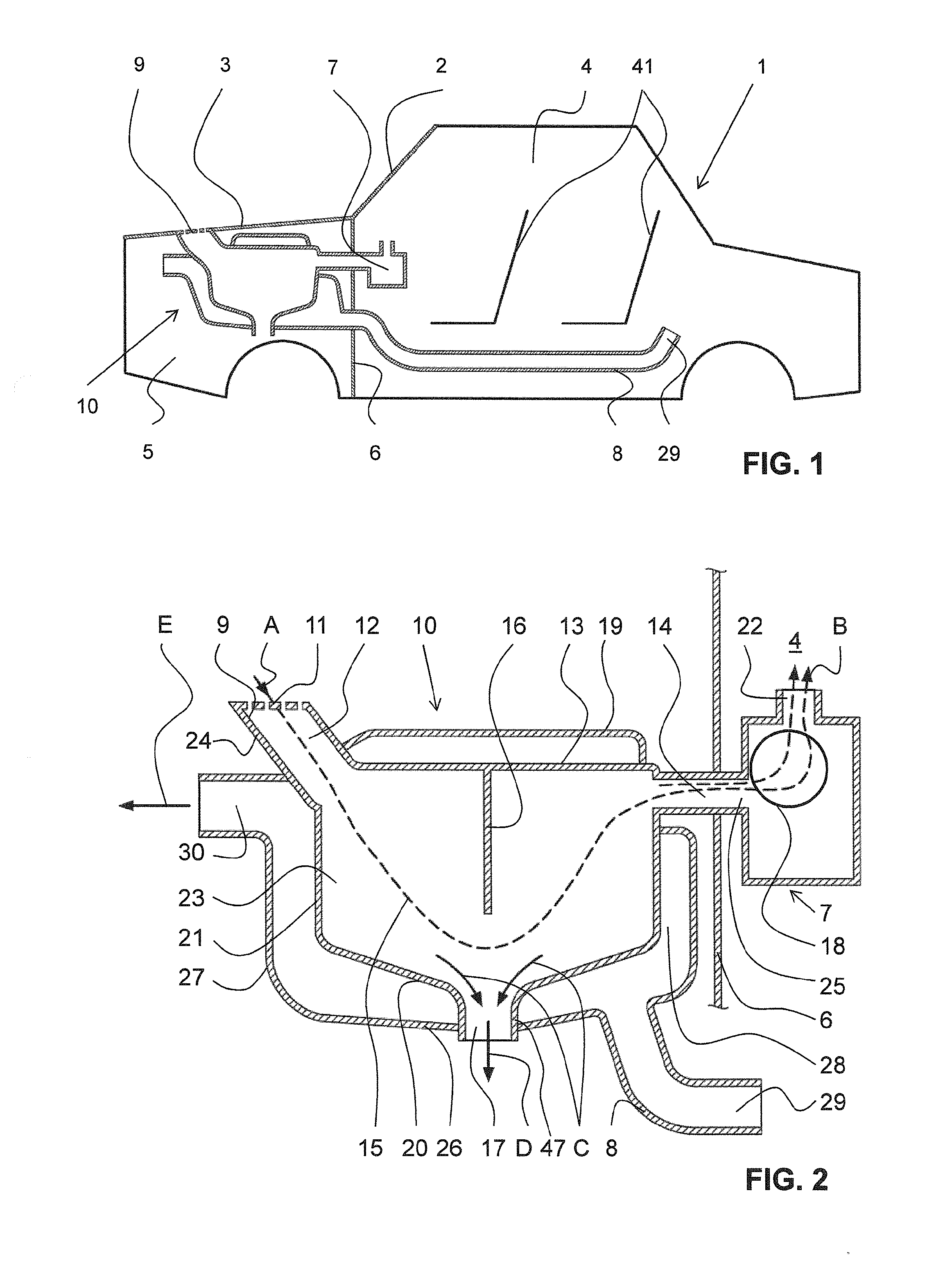
[0047]FIG. 1 illustrates schematically a motor vehicle 1, in which a water box 10 in accordance with a first embodiment according to the invention is provided. The water box 10 is accommodated in the engine compartment 5 of the motor vehicle 1 and has an air inlet opening 9, which opens to the outside in the region of an engine hood 3. Fresh air can be drawn through the air inlet opening 9 and through the interior of the water box 10 by an air conditioning unit 7, and this air is passed from the air conditioning unit 7 into the passenger compartment 4. In comparison with the water box 10, the air conditioning unit 7 is arranged on the opposite side of a bulkhead 6, which separates the engine compartment 5 from the passenger compartment 4. Normally, the air conditioning unit 7 is arranged in the dashboard or in a frontal area in the passenger compartment 4 of the motor vehicle 1. The air inlet opening 9 could also be arranged at any other position in the motor vehicle 1, in particula...


PUM

PropertyMeasurementUnit
Thicknessaaaaaaaaaa
Thicknessaaaaaaaaaa
Temperatureaaaaaaaaaa

Abstract

The invention relates to a water chamber (10) for a motor vehicle (1), which water chamber has a wall (13, 20, 21), which defines a first interior (23). The water chamber (10) also has at least one air inlet opening (9), through which air can flow into the first interior (23), and at least one air outlet opening (25), through which air can flow out of the first interior (23). A water outlet opening (17) is also present, which is suitable for removing water from the first interior (23). The water chamber (10) is designed as a heat exchanger, comprising a heat exchange element (13, 20, 21; 16′), which is used to transfer thermal energy from exhaust air into the first interior (23). The water chamber also has a structure (8, 26, 27, 40; 8′) that is used to conduct exhaust air to the heat exchange element (13, 20, 21; 16′) in a controlled manner.

Description

TECHNICAL FIELD[0001]The present invention relates to a water box for a motor vehicle, a method for controlling the temperature of a water box and a motor vehicle having a water box. Water boxes are used in motor vehicles to separate water from air drawn in by an air conditioning unit.PRIOR ART[0002]To heat or cool the air in the passenger compartment, the normal practice in the case of motor vehicles is for fresh air to be drawn in from the outside and fed to the passenger compartment by means of an air conditioning unit. An air conditioning unit has at least one evaporator and / or a heater, by means of which the fresh air can be cooled or heated to a desired temperature. It can furthermore include an air delivery unit, such as, in particular, a fan, to draw in the air.[0003]To enable fresh air that is as dry and free of droplets as possible to be made available to the air conditioning unit, a water box is generally provided in motor vehicles. The purpose of the water box is to sepa...

Claims


Application Information

Patent Timeline
IPC IPC(8): B60H1/00B01D45/08F24F3/16
CPCB60H1/00021B01D45/08F24F3/16B60H1/00321B60H1/28B60H2001/00214B60H1/039
Inventor HARKE, STEFAN
Owner WEIDPLAS
Why Eureka
Try Eureka