
Computer-implemented land planning system and method with gis integration

a technology of integrated planning and computer implementation, applied in computer aided design, data processing applications, instruments, etc., can solve the problems of time-consuming, inaccurate, expensive, and time-consuming of the most common today, and the current process is getting even more complex and expensiv

Active Publication Date: 2015-06-04
BENTLEY SYST INC
View PDF3 Cites 12 Cited by
  • Summary
  • Abstract
  • Description
  • Claims
  • Application Information

AI Technical Summary

Benefits of technology

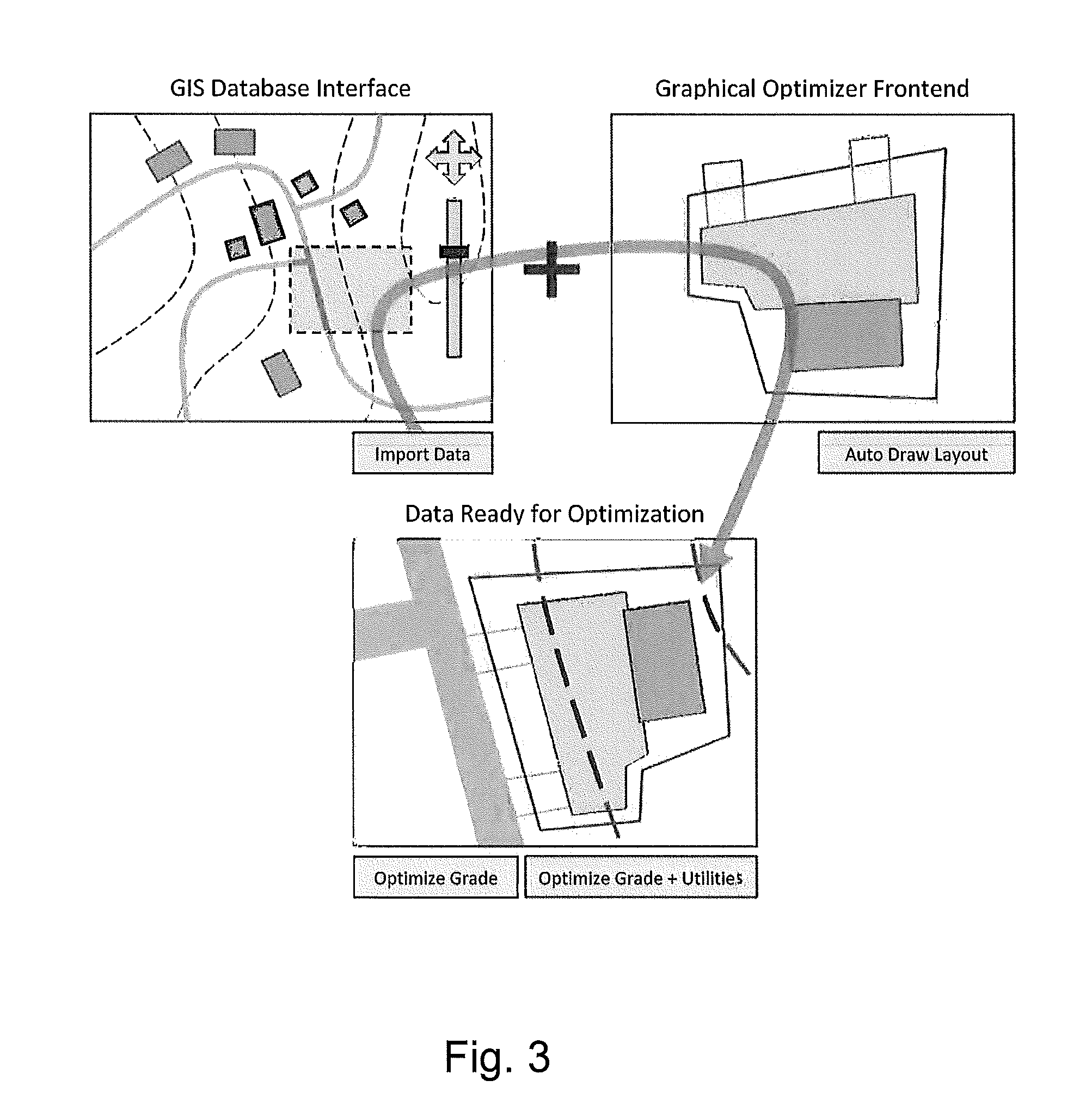
The present invention is a computer-implemented land planning system and method that can automatically generate a conceptual fit solution to a user-defined land development problem. The system utilizes GIS technology and accesses data from a GIS database. It employs a heuristic problem-solving strategy, such as evolutionary algorithms, to determine which options are best based on cost and / or revenue. The system can perform land planning and engineering simultaneously, and it can shorten the time it takes to get a final engineering drawing. The system also provides technology that allows land developers to determine the most cost-effective way to develop a land site and minimize the risk associated with developing a land site. It can minimize the initial investment capital required for developing a land site and lower engineering costs. The system can effectively integrate the creative and engineering sides of land planning and development to achieve a very good or even globally optimal solution.

Problems solved by technology

The process commonly used today by professional real estate developers, corporations, government entities and others to assess land for engineering feasibility, cost of developing, and investment purposes is time consuming, inaccurate, and expensive.
Unfortunately, the current process is getting even more complex and expensive due to added bureaucratic complications with land use zoning, environmental protection requirements, extended permitting processes, as well as the availability and escalating cost of land in desirable areas.
This problem affects a broad spectrum of land users including, for example, real estate developers (office / industrial, commercial, retail, residential), corporations which own and use real estate (public / private), and government entities (Federal, State, County, City).
This initial planning process can take from 2 days to four weeks, and usually results in a single schematic drawing with limited information (e.g., will the site support the building footprints or building lots and the necessary streets and / or parking lots?).
This process can take 2 weeks to 16 weeks and usually results in only one option that is based on the designer's experience but is not optimized in any respect.
Often times value engineering is required to bring the design back within the original budget.
The above planning process often must occur before the property is purchased, and requires substantial investment in legal fees and earnest money to hold the property for an extended length of time.
After this 4 week to 28-week process (average 16 weeks) and considerable expense and risk of lost opportunity, the developer must assess the risk of purchasing and developing the property based on one un-optimized design option.
Unfortunately, the process outlined above is complicated even further by miscommunication and disconnect between the many groups involved, which often results in bad designs, bad budgets, disagreements, and bad projects.
Of all mandatory information needed for the conceptual design of a civil engineering site, the existing topography is generally the most difficult to readily and accurately obtain.
This often means that civil engineers cannot generate a grading plan for the site at that stage, which means the cost for grading that site is guessed instead and often highly inaccurate.
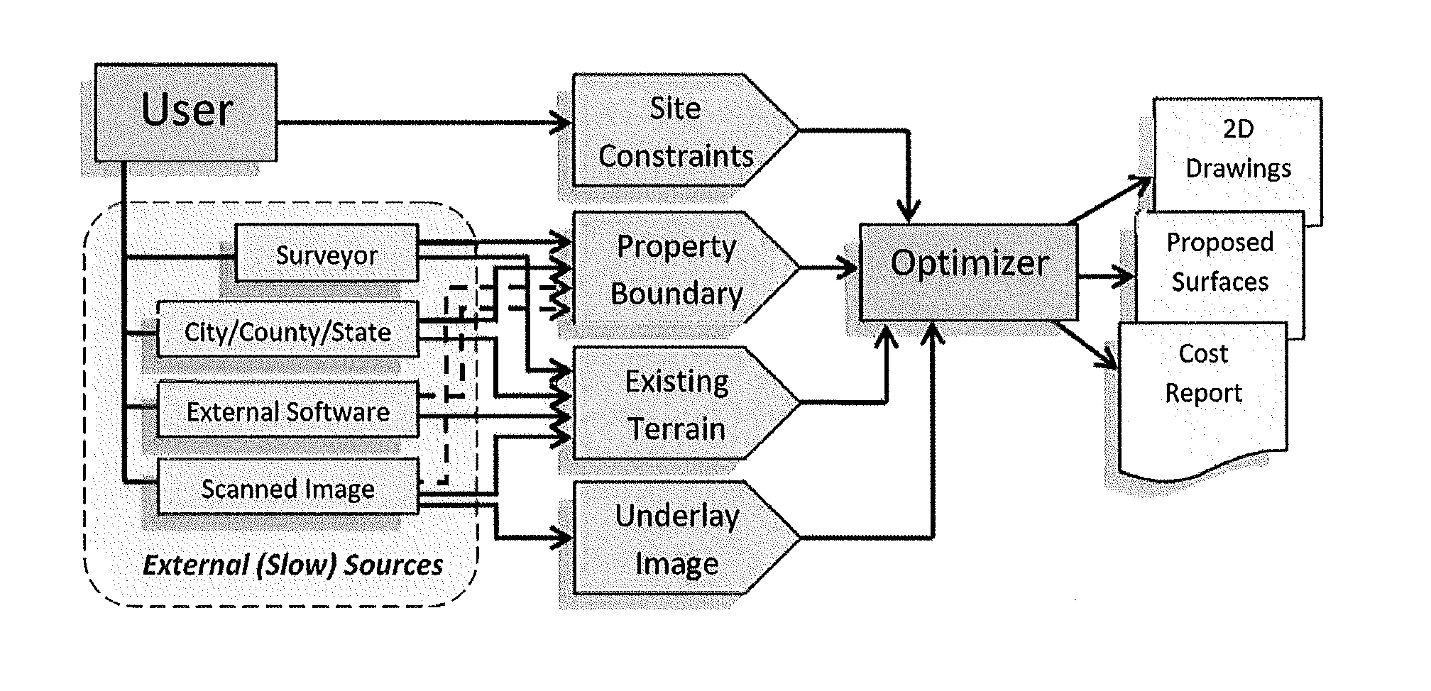
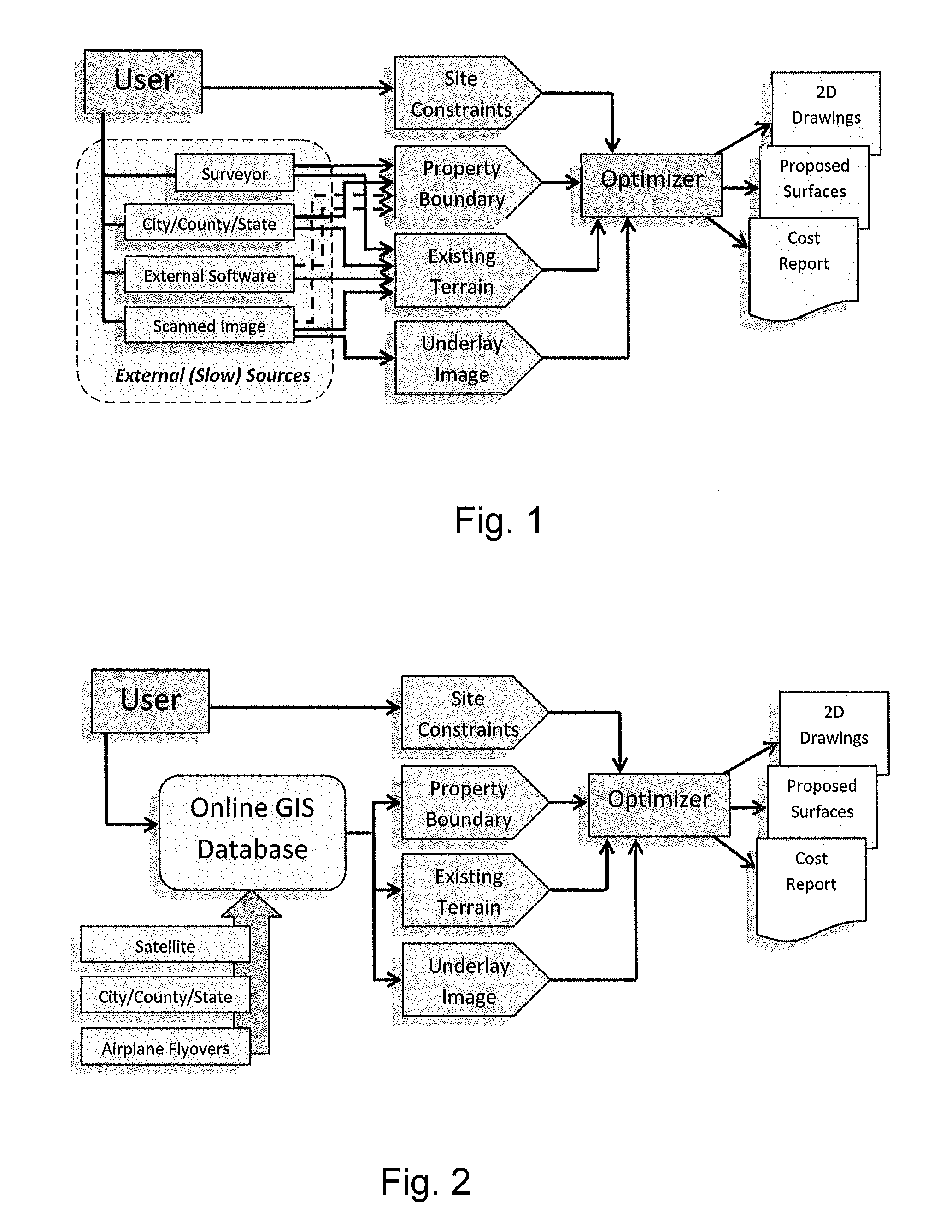
A surveyor can physically go to a site and use his measuring equipment to generate an exact parcel map and give different levels of detail on the existing topography of the site, this is usually expensive and slow.
This can be difficult to find, can be expensive, and may require specialists to convert the data correctly.
Some external software may exist for group different topographical databases, but the output of these products is also difficult or infeasible to integrate with an Optimizer.
While this may be feasible, it clearly is not ideal.
Such processes are slow, often inaccurate and often not up to date.
The amount of data in these GIS databases is increasing at a substantial rate and they are becoming increasingly sophisticated.

Method used


Image

  • Computer-implemented land planning system and method with gis integration
  • Computer-implemented land planning system and method with gis integration
  • Computer-implemented land planning system and method with gis integration

Examples


Embodiment Construction

[0015]Various exemplary embodiments of the present invention are described below. Use of the term “exemplary” means illustrative or by way of example only, and any reference herein to “the invention” is not intended to restrict or limit the invention to exact features or steps of any one or more of the exemplary embodiments disclosed in the present specification. References to “exemplary embodiment,”“one embodiment,”“an embodiment,”“various embodiments,” and the like, may indicate that the embodiment(s) of the invention so described may include a particular feature, structure, or characteristic, but not every embodiment necessarily includes the particular feature, structure, or characteristic. Further, repeated use of the phrase “in one embodiment,” or “in an exemplary embodiment,” do not necessarily refer to the same embodiment, although they may.

[0016]It is also noted that terms like “preferably”, “commonly”, and “typically” are not utilized herein to limit the scope of the claime...


PUM


Abstract

A computer-implemented land planning system is designed to generate at least one conceptual fit solution to a user-defined land development problem. The system employs a computer readable medium and a computer program encoded on the medium. The computer program is operable, when executed on a computer, for electronically creating at least one candidate solution to the land development problem. The candidate solution incorporates a plurality of engineering measurements applicable in development of an undeveloped land site. Existing GIS data is collected for the selected undeveloped land site. A fitness function quantitatively evaluates the candidate solution based on its cost. A heuristic problem-solving strategy manipulates the engineering measurements of the candidate solution to achieve a more quantitatively fit solution to the land development problem. Documentation illustrating the fit solution to the land development problem is delivered to the user.

Description

TECHNICAL FIELD AND BACKGROUND OF THE DISCLOSURE[0001]This disclosure relates broadly and generally to a computer-implemented land planning System and Method, such as that designed to generate one or more conceptual fit solutions to a user-defined land development problem. In exemplary embodiments described herein, the “problem” is expressed in terms of optimizing land development based on costs and budget constraints. Alternatively, the present disclosure may focus on other economic considerations such as return on investment (ROI). One example described below relates to the planning and development of a single pad commercial site. The present concept, however, is equally applicable to the planning and development of multi-pad commercial, mixed use, and residential sites, communications easements, roadways and railways, and the like.[0002]Modern Geographical Information System (GIS) technologies use digital information, for which various digitized data creation methods are used. Th...

Claims


Application Information

Patent Timeline
IPC IPC(8): G06F17/50
CPCG06F17/50G06Q10/06G06Q50/08G06F30/13G06F30/00G06Q10/0637G06Q50/165
Inventor DETWILER, MICHAEL W.REYNOLDS, JR., JAMES W.WATTS, ANTHONY H.BAECK, THOMASBREUKELAAR, RON
Owner BENTLEY SYST INC
Learn More