White organic light emitting device

a light-emitting device and organic technology, applied in the direction of organic semiconductor devices, thermoelectric devices, solid-state devices, etc., can solve the problems of inability to achieve the same level of efficiency as a traditional monochromatic organic light-emitting device, inability to adjust the structure for enhancing performance, and inability to achieve the same level of efficiency. , to achieve the effect of improving light efficiency

Inactive Publication Date: 2015-06-04
SHENZHEN CHINA STAR OPTOELECTRONICS TECH CO LTD
View PDF5 Cites 2 Cited by
  • Summary
  • Abstract
  • Description
  • Claims
  • Application Information

AI Technical Summary

Benefits of technology

[0004]In view of the shortcoming of the conventional technology, a primary object of the invention is to provide a white organic light-emitting device with ideal chromaticity coordinates value and better light efficiency.

Problems solved by technology

However, one of the difficult points for implementing this technology is that the white organic light-emitting device is unable to reach the same level of efficiency as a traditional monochromatic organic light-emitting device does.
Meanwhile, when manufacturing a white organic light-emitting device, two or three forms of phosphors will be mixed inside the device, thus the internal structure of the device is relatively more complicated.
In contrast, in the case of using a white organic light-emitting device as the light source, because the device has a more complex internal structure, adjusting the structure for enhancing performance is more difficult or the adjustment has to be done by forming an optical micro-cavity with a complex reflection structure.
Besides, because the white organic light-emitting device has a complex structure, the error tolerant capability of the manufacturing technology for white organic light-emitting devices is relatively limited, thus yield rate is not easy to improve and the cost is relatively high.

Method used


Image

  • White organic light emitting device
  • White organic light emitting device
  • White organic light emitting device

Examples


first embodiment

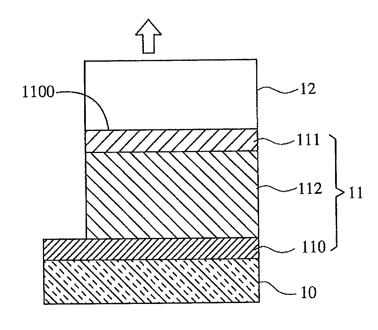
[0024]With reference to FIG. 1, FIG. 1 is a schematic view of the structure of a white organic light-emitting device according to the present invention. The white organic light-emitting device mainly comprises a substrate 10, an organic light-emitting unit 11 and an efficiency-enhancing layer 12.

[0025]The substrate 10 is a transparent substrate, such as a glass substrate.

[0026]The organic light-emitting unit 11 includes a first electrode 110, a second electrode 111 and an organic layer 112. The first electrode 110 is disposed on the substrate 10 and may be an indium tin oxide layer. The second electrode 111 is disposed opposite to the first electrode 110. The organic layer 112 is disposed between the first electrode 110 and the second electrode 111. As shown in FIG. 1, in this embodiment, the first electrode 110 is an anode, and the second electrode 111 is a cathode. The organic light-emitting unit 11 has a light-emitting direction that is from the second electrode 111 to the first ...

third embodiment

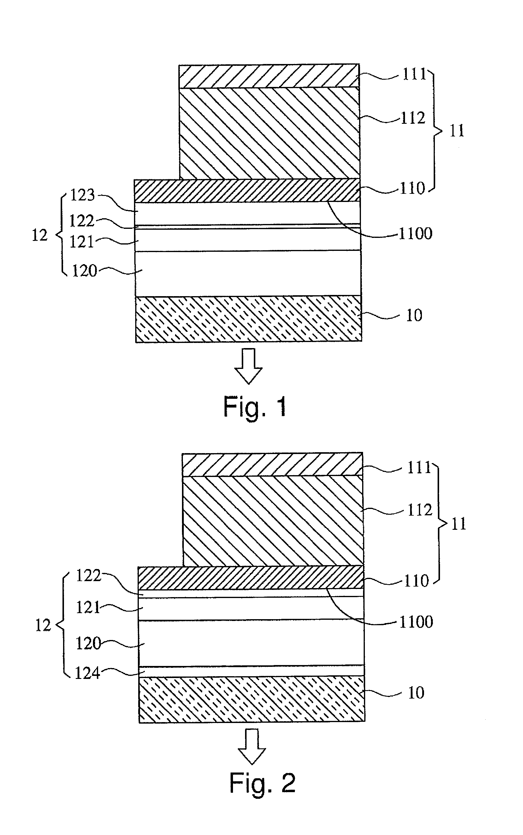
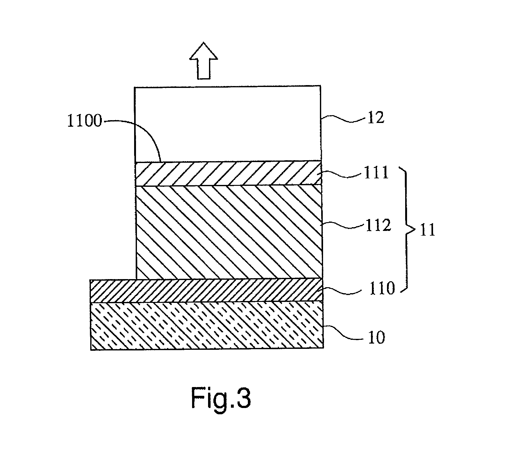
[0033]The efficiency-enhancing layer of the white organic light-emitting device of the present invention is not limited to be mounted only between the first electrode 110 and the substrate 10 as shown in FIG. 2 or FIG. 1. With reference to FIG. 3, FIG. 3 is a schematic view of the structure of a white organic light-emitting device according to the present invention. The embodiment in FIG. 3 differs from the embodiment in FIG. 1 in that the first electrode 110 is an anode; the second electrode 111 is a cathode, and the organic light-emitting unit 11 has a light-emitting direction that is from the first electrode 110 to the second electrode 111. Therefore the light-emitting surface of the organic light-emitting unit 11 is located at a surface of the second electrode 111, and therefore the efficiency-enhancing layer 12 is disposed on the second electrode 111.

[0034]In conclusion, the present invention is mainly to form an efficiency-enhancing layer on a light-emitting surface of an orga...


PUM


Abstract

The present invention provides a white organic light-emitting device having a substrate, an organic light-emitting unit and an efficiency-enhancing layer. The organic light-emitting unit has a first electrode, a second electrode and an organic layer. The first electrode is disposed on the substrate. The second electrode is disposed opposite to the first electrode. The organic layer is disposed between the first electrode and the second electrode. The efficiency-enhancing layer is disposed on a light-emitting surface of the organic light-emitting unit. The efficiency-enhancing layer can effectively adjust the chromaticity coordinates value and improve light efficiency of the white organic light-emitting device so that directly adjusting the internal structure of the organic light-emitting unit can be avoid.

Description

FIELD OF THE INVENTION[0001]The present invention relates to a light-emitting device for display device, and more particularly to a white organic light-emitting device.BACKGROUND OF THE INVENTION[0002]Nowadays, in flat-panel display industry, the resolution required for AMOLED display panels is steadily increasing, and demand for large-sized AMOLED display panels is also increasing. In order to achieve the foregoing requirement, a kind of display device using white organic light-emitting devices with a color filter is being developed. However, one of the difficult points for implementing this technology is that the white organic light-emitting device is unable to reach the same level of efficiency as a traditional monochromatic organic light-emitting device does. Meanwhile, when manufacturing a white organic light-emitting device, two or three forms of phosphors will be mixed inside the device, thus the internal structure of the device is relatively more complicated. In the conditio...

Claims


Application Information

Patent Timeline
Patent Type & Authority Applications(United States)
IPC IPC(8): H01L51/52H01L51/00
CPCH01L51/5262H01L51/0096H01L2251/308H01L2251/306H01L2251/558Y02E10/549H10K50/858H10K50/85H10K77/10H10K2102/102H10K2102/103H10K2102/351
Inventor LIU, CHIH-CHE
Owner SHENZHEN CHINA STAR OPTOELECTRONICS TECH CO LTD
Why Eureka
Try Eureka