Multi-channel conduit and method for heating a fluid for use in hydraulic fracturing

a technology of hydraulic fracturing and conduits, applied in the direction of lighting, heating apparatus, insulation, etc., can solve the problems of fuel delivery and storage of flammable materials, and achieve the effect of reducing the cost of fuel delivery and storag

Inactive Publication Date: 2015-06-11
FREEDOM OILFIELD SERVICES
View PDF7 Cites 46 Cited by
  • Summary
  • Abstract
  • Description
  • Claims
  • Application Information

AI Technical Summary

Benefits of technology

[0004]The present invention relates to a fluid heating device capable of heating water in a fra

Problems solved by technology

It also requires the added cost of fuel delivery and storage of flammable materials, and

Method used


Image

  • Multi-channel conduit and method for heating a fluid for use in hydraulic fracturing
  • Multi-channel conduit and method for heating a fluid for use in hydraulic fracturing
  • Multi-channel conduit and method for heating a fluid for use in hydraulic fracturing

Examples


Embodiment Construction

[0019]Although the disclosure hereof is detailed and exact to enable those skilled in the art to practice the invention, the physical embodiments herein disclosed merely exemplify the invention which may be embodied in other specific structures. While the preferred embodiment has been described, the details may be changed without departing from the invention, which is defined by the claims.

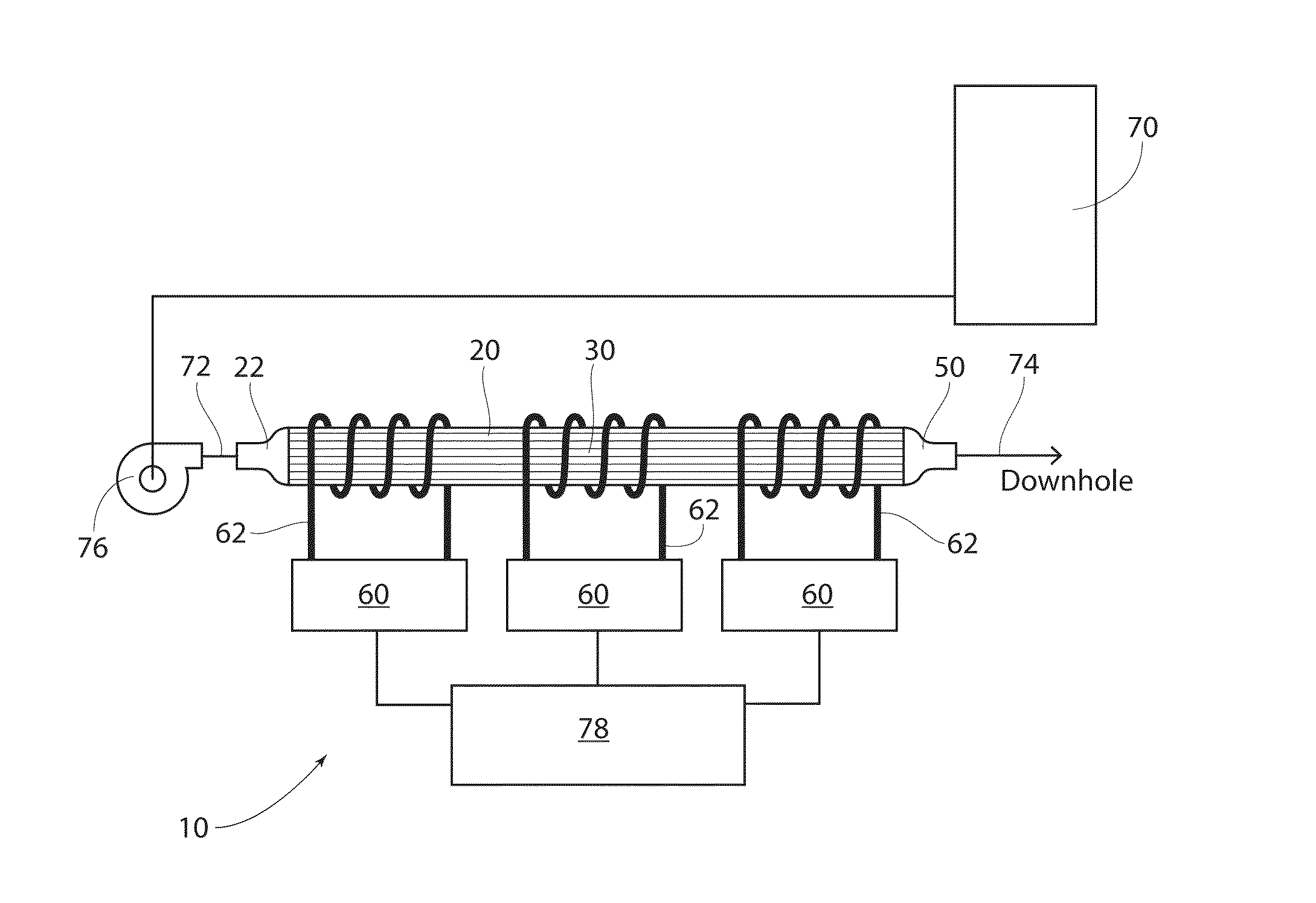
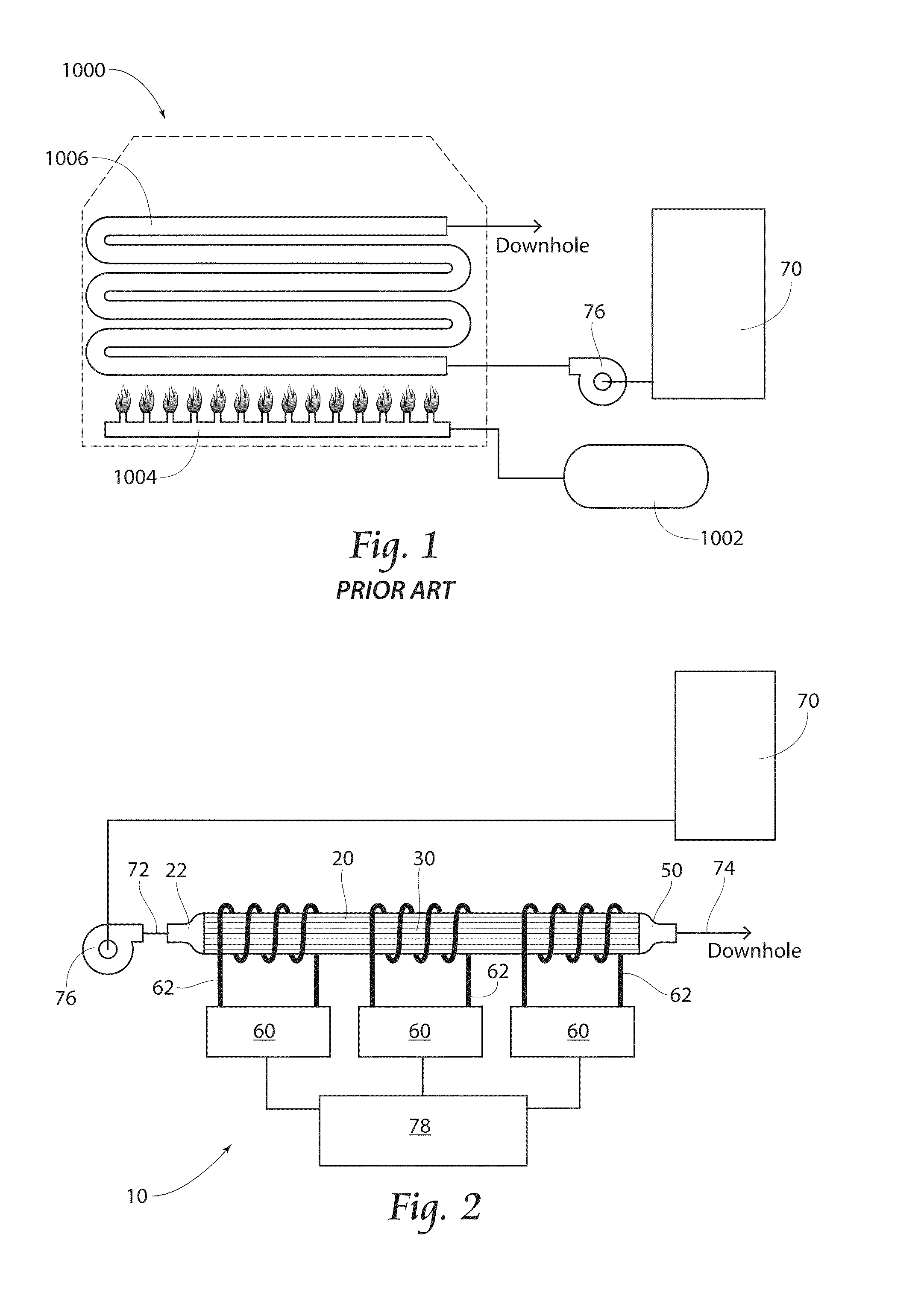
[0020]FIG. 1 depicts a prior method and device 1000 for heating a fluid in a fracing system. Here a fluid, in this case water (not shown), is taken from a water source 70 and pumped by a pump 76 into a burner box 1000. The burner box 1000 houses propane burners 1004 and a coil 1006. The water flows through the coil 1006 and is heated by the propane burners1004 with propane (not shown) supplied from a propane tank 1002. The water then exits the burner box 1000 and continues downhole. As mentioned earlier, this system requires an open flame and a substantial amount of propane to heat the water flowi...


PUM


Abstract

System and method directed to the art of heating a fluid for use in a hydraulic fracturing system. A heat tube having a plurality of pipes disposed axially along and substantially near the periphery of a medial portion of the heat tube. The heat tube is heated by induction heaters.

Description

BACKGROUND OF THE INVENTION[0001]Hydraulic fracturing, commonly referred to as “fracing,” is a method of extracting hydrocarbons from a geological formation deep within the earth. The process entails a combination of drilling vertically and horizontally into the earth; introducing a mixture of water, a proppant (typically sand) to hold open the fractures, and optionally a chemical mixture to reduce equipment wear and to aid in the removal of the hydrocarbons; and building the pressure within the wellbore with the mixture until a sufficient pressure is achieved causing the formation to fracture, thus releasing the hydrocarbons which can be removed via the wellbore.[0002]Water is an important element in the fracing process as it carries the proppant and chemicals deep into the earth. Thus the properties of the water, specifically temperature, can make a difference in overall fracing performance and efficiency. Achieving a proper water temperature may reduce the amount of chemicals nee...

Claims


Application Information

Patent Timeline
IPC IPC(8): F24H1/00H05B6/36E21B36/00
CPCF24H1/0018H05B6/36E21B36/00H05B6/108F24H1/08F24H1/142F24H2250/08E21B43/26E21B36/04E21B43/2607
Inventor HOLT, ARTHUR H.
Owner FREEDOM OILFIELD SERVICES
Why Eureka
Try Eureka