Laser transmitting circuit, laser receiving circuit, distance calculation circuit and devices thereof

Inactive Publication Date: 2015-06-11
CHONGQING AITE OPTICAL & ELECTRONICS
View PDF3 Cites 3 Cited by
  • Summary
  • Abstract
  • Description
  • Claims
  • Application Information

AI Technical Summary

Benefits of technology

[0012]In the technical solutions provided by the present invention, the laser transmitting circuit allows taking full advantageous of the laser transmitting tube so that the laser transmission power is improved and the measurement range of the rangefinder is increased. In addition, in the technical solutions provided by the present i

Problems solved by technology

As the time required to turn on or off the avalanche transistors is relatively long and the peak pulse current (Ip=10 A) is relatively small, the pulse current provided for a laser transmitting tube is reduced and the peak power of laser transmitted by the laser transmitting tube cannot reach its rated value, so that the laser transmitting tube is underutilized.
As a result, the distance measurement capability of a semiconductor laser rangefinder is weaken

Method used


Image

  • Laser transmitting circuit, laser receiving circuit, distance calculation circuit and devices thereof
  • Laser transmitting circuit, laser receiving circuit, distance calculation circuit and devices thereof
  • Laser transmitting circuit, laser receiving circuit, distance calculation circuit and devices thereof

Examples


Embodiment Construction

[0024]Embodiments of the present invention will be described in detail as below. The examples of the embodiments will be illustrated by the accompanying drawings in which same or similar reference numbers represent same or similar elements or elements with same or similar functions. The embodiments described as below with reference to the drawings are exemplary only for explaining the present invention and shall not be interpreted as any limitation to the present invention.

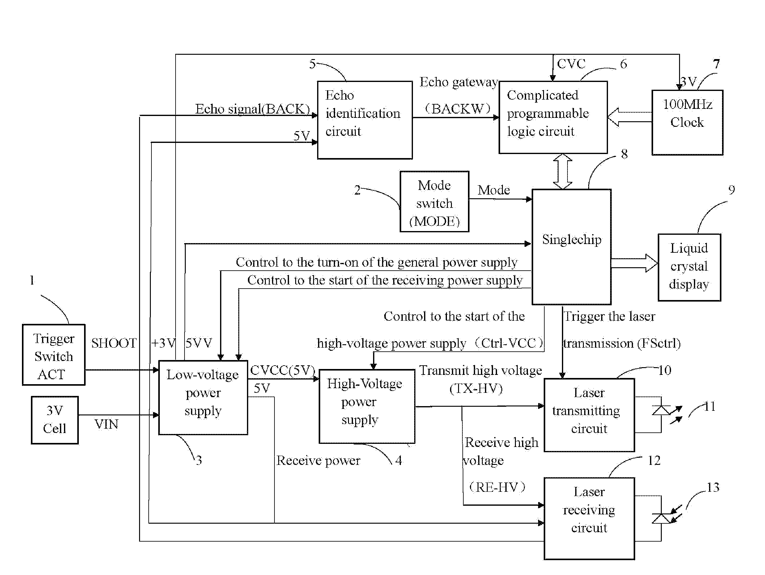
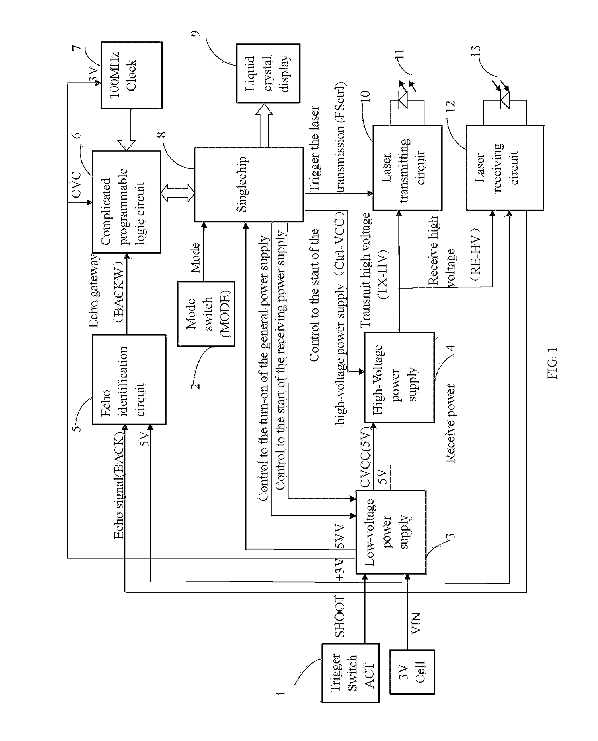
[0025]As shown in FIG. 1 is a block diagram for the overall principle of circuits of a semiconductor laser rangefinder according to the present invention, in which: 1—Trigger switch; 2—Mode switch; 3—Low-voltage power supply; 4—High-voltage power supply; 5—Echo identification circuit; 6—Programmable logic circuit; 7—Clock source; 8—Singlechip; 9—Liquid crystal display; 10—Laser transmitting circuit; 11—Laser transmitting tube; 12—Laser receiving circuit; and, 13—Laser receiving tube.

[0026]In FIG. 1, as an embodime...


PUM


Abstract

The present invention provides a laser transmitting circuit, a laser receiving circuit, a distance calculation circuit and devices thereof. The laser transmitting circuit comprises an energy storage capacitor, a laser transmitting tube, an MOS switch circuit and an MOS switch driving circuit. The laser receiving circuit comprises a laser receiving tube, a first low-noise triode, a second low-noise triode and a low-noise wideband amplifier. The distance calculation circuit comprises a singlechip, a programmable logic circuit, a clock source and an echo identification circuit. The present invention further provides a low-voltage power circuit that provides a reverse polarity protection to an external power supply without additional diode connected in reverse polarity. According to the technical solutions provided by the present invention, the measurement range and precision of a semiconductor laser rangefinder can be improved effectively.

Description

TECHNICAL FIELD[0001]The present invention relates to the field of laser distance measurement, particularly to a laser transmitting circuit, a laser receiving circuit, a distance calculation circuit and devices thereof.BACKGROUND ART[0002]As an instrument for accurately measuring the distance of a target via laser, a laser rangefinder transmits an elliptical, conical laser beam to a target during working. The laser reflected by the target is received by a photoelectric element. A timer measures the time taken from initial transmission to final reception of the laser beam, so that the distance from the observer to the target is calculated. Semiconductor laser rangefinders have advantages of low weight, small size, low power consumption and simple operation. For a semiconductor laser rangefinder in the prior art, its electronic circuitry also includes a laser transmitting circuit, a laser receiving circuit and a mainboard circuit for calculating distance.[0003]In a laser transmitting ...

Claims


Application Information

Patent Timeline
IPC IPC(8): G01C3/08G01S7/484G01S17/08G01S7/4861G01S17/10
CPCG01C3/08G01S7/484G01S17/08G01S7/486G01S7/4861G01S17/14G01S17/10G01S7/4873
Inventor XU, RIXINWANG, SHUNDE
Owner CHONGQING AITE OPTICAL & ELECTRONICS
Why Eureka
Try Eureka