
Solution method and solution apparatus for underdetermined system of linear equations

a linear equation and solution method technology, applied in the field of solution methods and solutions for solving systems of linear equations, can solve the problem of large number of additional observation signals, and achieve the effect of reducing the observation rate and high degree of estimation precision

Inactive Publication Date: 2015-06-11
CANON KK
View PDF4 Cites 0 Cited by
  • Summary
  • Abstract
  • Description
  • Claims
  • Application Information

AI Technical Summary

Benefits of technology

The purpose of this patent is to provide a solution that enables higher precision in estimating a certain phenomenon with a smaller number of observation signals.

Problems solved by technology

This means that a large number of additional observation signals is required in response to even a small increase in the number of non-zero elements in the signal.

Method used


Image

  • Solution method and solution apparatus for underdetermined system of linear equations
  • Solution method and solution apparatus for underdetermined system of linear equations
  • Solution method and solution apparatus for underdetermined system of linear equations

Examples


embodiment

[0044]A preferred embodiment of the solution method and solution apparatus according to the present invention will be described in detail below with reference to the drawings.

[0045](Configuration of Solution Apparatus)

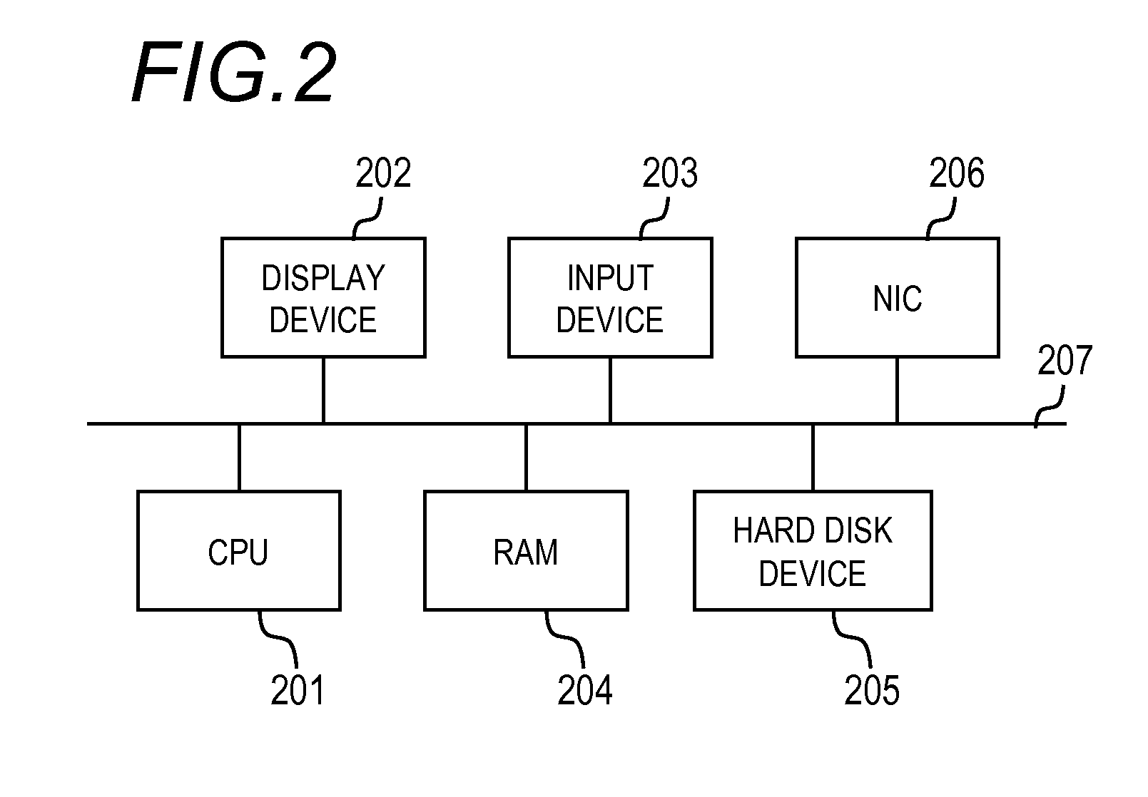
[0046]FIG. 2 is a block diagram showing a basic configuration of a computer that functions as a solution apparatus according to an embodiment of the present invention. The computer is mainly constituted by a CPU 201, a display device 202, an input device 203, a RAM 204, a hard disk device 205, an NIC 206, and so on, which are connected to each other via a bus 207.

[0047]The CPU (Central Processing Unit) 201 performs overall control of the apparatus using programs and data stored in the RAM (a main memory) 204, and executes various processing described below. The display device 202 is constituted by a liquid crystal display or the like, and is capable of displaying processing results (an obtained solution, a reconstructed image) obtained by the CPU 201 in the form of alp...

modified example

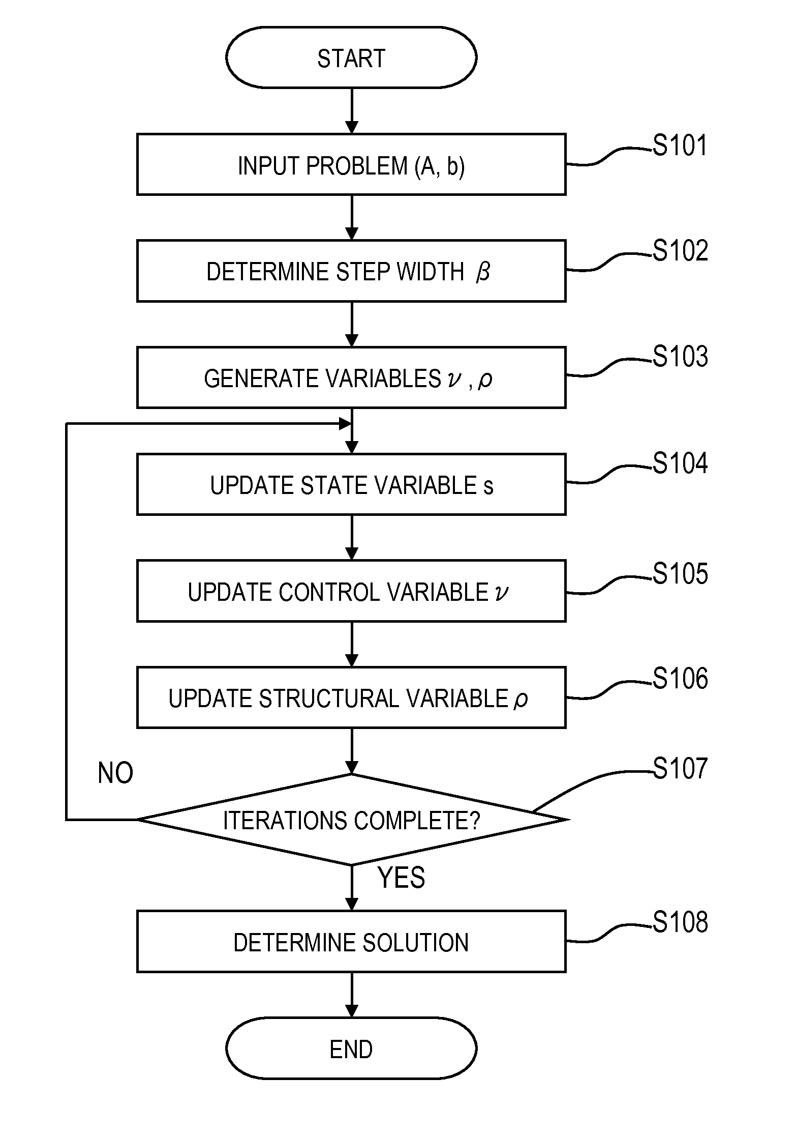
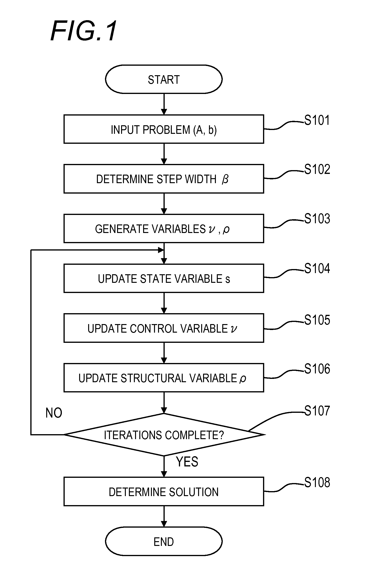
[0073]In the flow of FIG. 3, the processing (Equation (13)) for updating the state variable s in the state variable updating step S104 is executed only once, but the updating processing of step S104 is preferably executed a plurality of times. In other words, the value of the state variable s is updated a plurality of times while the value of the structural variable ρ remains fixed. In so doing, a more favorable performance may be obtained. The number of updates may be set in advance at five or ten, for example, or maybe varied dynamically. As a method of dynamically varying the number of updates, repetition of the updating processing may be stopped on the basis of the values of the objective function L2 and the residual norm, variation rates thereof, and so on, for example, similarly to the condition determination of step S107.

[0074]The processing for updating the structural variable ρ in the structural variable updating step S105 is likewise preferably executed a plurality of time...


PUM


Abstract

A variable to be determined is expressed as a product of a state variable and a structural variable for each element. The structural variable is a monotonically increasing function of a control variable that takes a real number value, and is thus limited to a real number of 0 to 1. An objective function defined as a function of the state variable and structural variable or the state variable and control variable is used. In each iteration, a computer executes: a state variable updating step of updating a value of each element of the state variable on the basis of information of the objective function with respect to the state variable; and a structural variable updating step of updating a value of each element of the structural variable on the basis of information of the objective function with respect to said structural variable.

Description

BACKGROUND OF THE INVENTION[0001]1. Field of the Invention[0002]The present invention relates to a solution method and a solution apparatus for solving a system of linear equations, and more particularly to a technique of solving an underdetermined system of linear equations in which the number of equations is smaller than the number of variables.[0003]2. Description of the Related Art[0004]In a medical instrument used for X ray computed tomography (CT), magnetic resonance imaging (MRI), or the like, a three-dimensional structure of the inside of a human body is reconstructed from an observation image projected onto a two-dimensional plane. When a three-dimensional structure to be estimated is set as an unknown vector x, an observation process such as X ray projection is set as a matrix A, and an observation signal is set as b, the observation process can be formulated as follows:Ax=b   (1)[0005]Here, A may also be referred to as a coefficient matrix, and b may also be referred to a...

Claims


Application Information

Patent Timeline
Patent Type & Authority Applications(United States)
IPC IPC(8): G06F17/12
CPCG06F17/12
Inventor WASHIZAWA, TERUYOSHI
Owner CANON KK
Learn More