Extended patellofemoral

a patellofemoral and extension technology, applied in the field of patellofemoral implants, can solve the problems of limited knee arthroplasty procedures, significant pain and potential damage to bone surfaces, and damage to the articular cartilage of the knee joint, so as to improve the implant coverage of each compartment, reduce anatomical variability, and reduce the effect of implant size and shap

Active Publication Date: 2015-06-18
STRYKER CORP
View PDF84 Cites 6 Cited by
  • Summary
  • Abstract
  • Description
  • Claims
  • Application Information

AI Technical Summary

Benefits of technology

[0006]The patellofemoral implants of the present invention improve implant coverage of each compartment of the distal femur for a larger percentage of the population. By designing the implants to only cover the region inside the condylopatellar border, anatomical variability reduces and less implant sizes and shape

Problems solved by technology

The articular cartilage of the knee joint may become damaged due to degeneration and/or wear, which may lead to bone-to-bone contact during articulation of the joint.
This may result in significant pain and potential damage to the bone surfaces

Method used


Image

  • Extended patellofemoral
  • Extended patellofemoral
  • Extended patellofemoral

Examples


Embodiment Construction

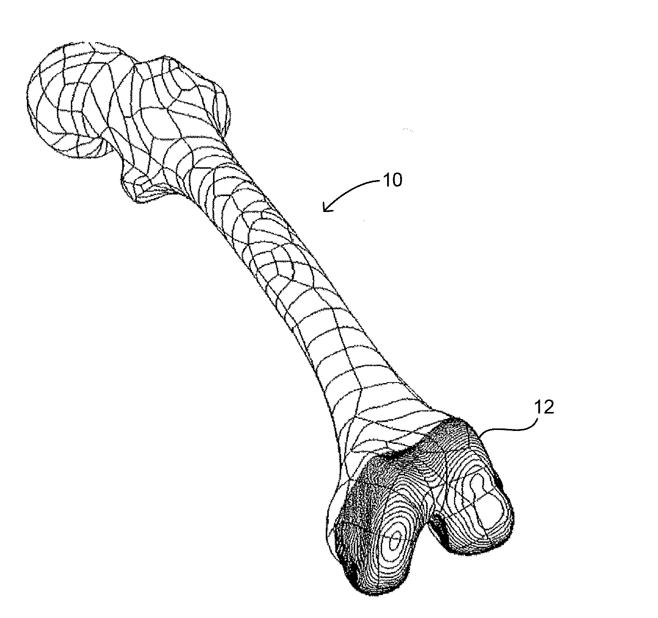
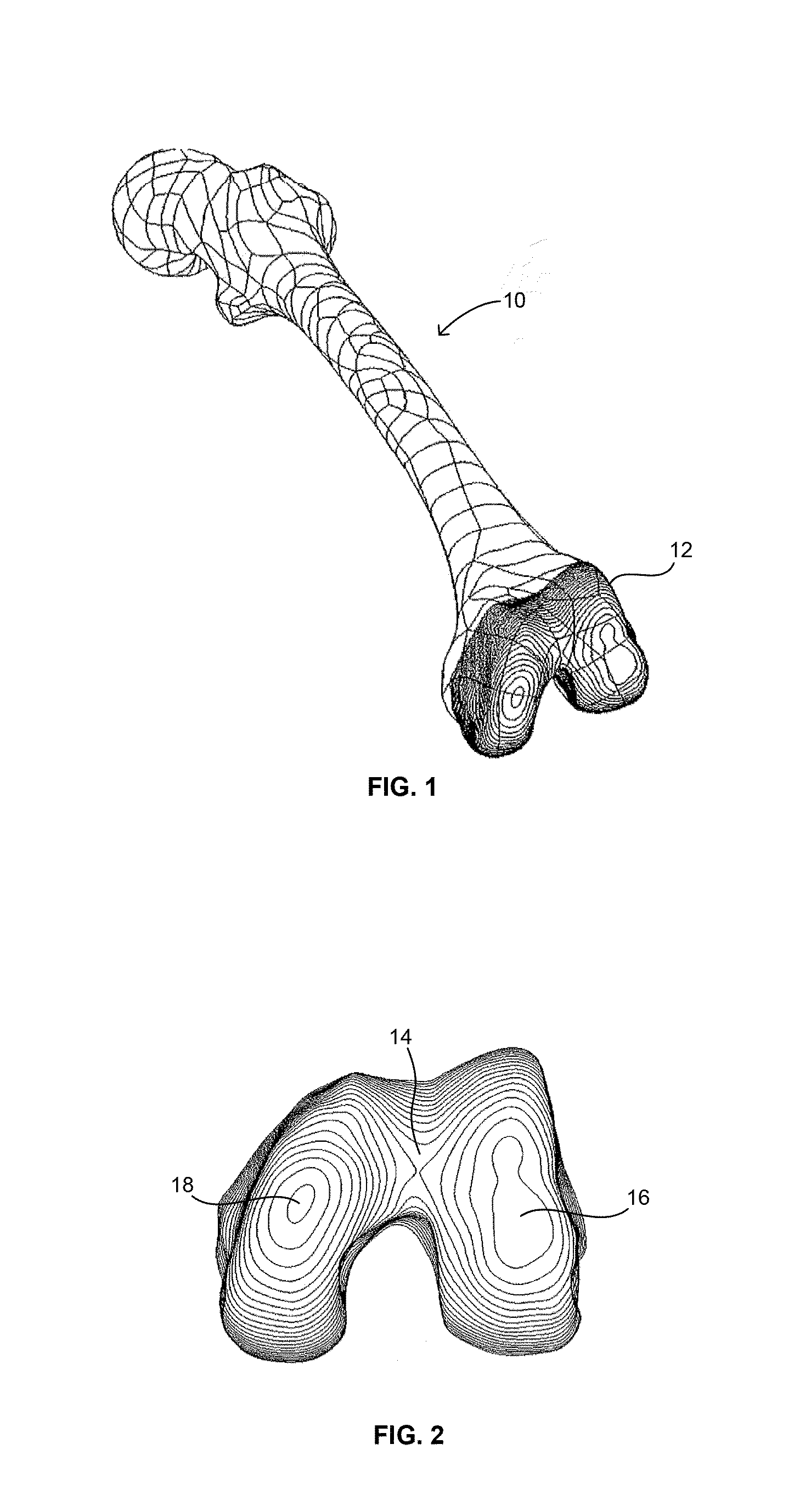
[0045]Referring to the drawings, wherein like reference numerals represent like elements, there is shown in the figures, in accordance with embodiments of the present invention, patellofemoral and condylar implants engaged to a resected distal end 12 of a femur, designated generally by reference numeral 10. FIGS. 1-2A are topographic isometric and distal views respectively of distal end 12 of femur 10 showing the contour of the outer surface thereof. As can be seen from these figures, femur 10 is a left femur having three regions, namely the trochlear groove 14, lateral condyle 16, and medial condyle 18. The topography of these areas or regions is referenced generally by the varying line curvature thereof.

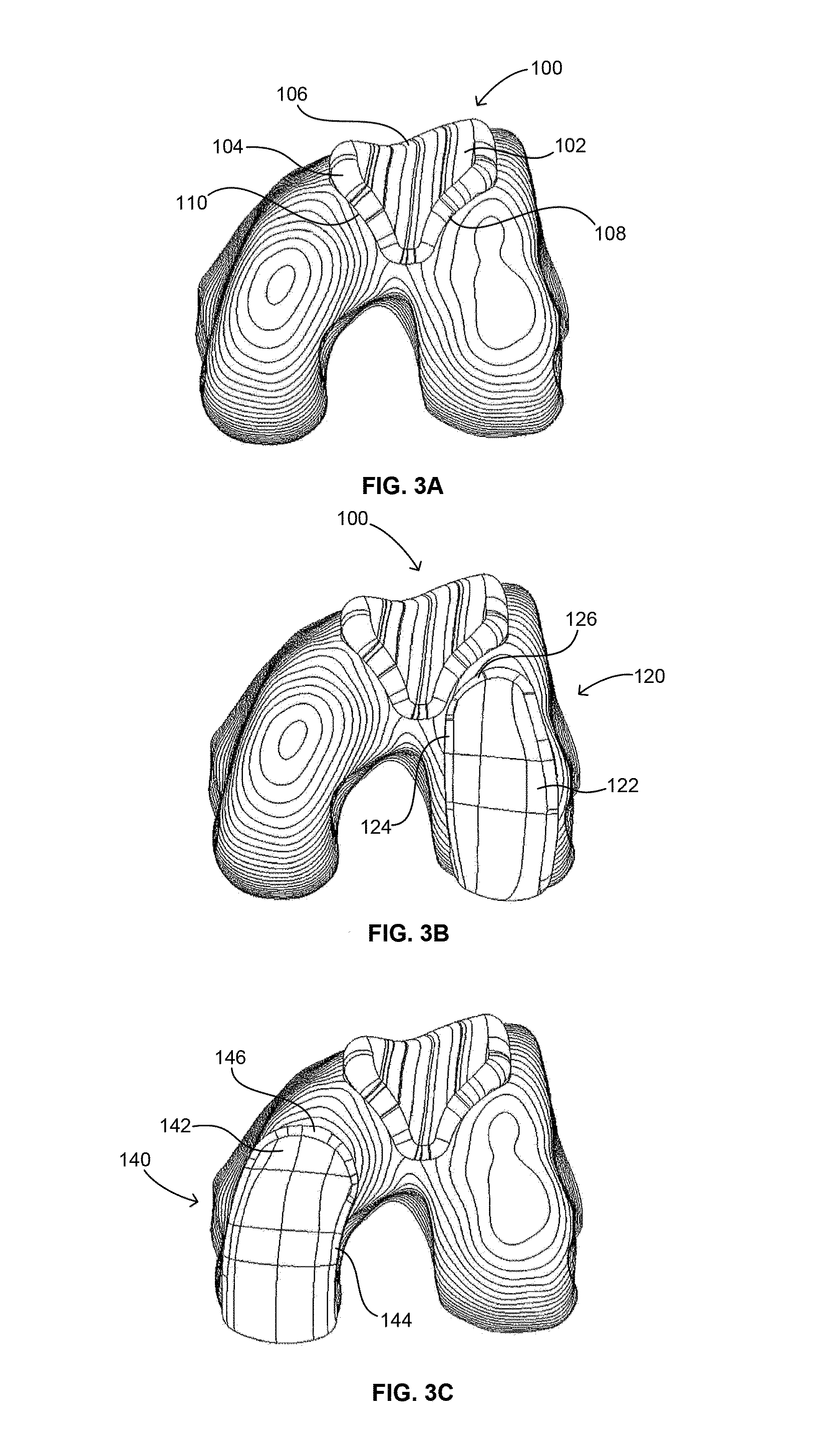
[0046]FIG. 3A is topographic distal view of a traditional patellofemoral implant 100 engaged to the distal end of the left femur shown in FIG. 1. Implant 100 includes an articular surface 102 having an outer periphery 104 and a trochlear groove 106, for example. Prior to being enga...


PUM


Abstract

Disclosed herein are knee replacement systems for replacing the articular surface of a distal femur. The systems include one or more unicompartmental components, namely patellofemoral, lateral condylar and medial condylar components. The components are configured such that when engaged to the femur the peripheries thereof do not cross specific locations and/or regions of the femur, namely the intercondylar notch and condylopatellar notch. The patellofemoral components described herein preferably have an extension portion extending posteriorly from a posterior periphery thereof towards an intercondylar notch or the femur without contacting the intercondylar notch of the femur when the patellofemoral component is engaged to the femur. The extension portion preferably extends posteriorly from posterior periphery of the patellofemoral component towards the condylopatellar notch of the femur without contacting the notch.

Description

FIELD OF THE INVENTION[0001]The present invention relates to patellofemoral implants and in particular relates to such implants having an extension portion designed to cover the medial and / or lateral aspect of the patellofemoral compartment posteriorly up to the intercondylar notch and condylopatellar notch.BACKGROUND OF THE INVENTION[0002]The knee joint includes three bones, namely the femur, tibia and patella. The distal end of the femur lies adjacent to the proximal end of the tibia while the patella lies adjacent the anterior portion of the femur. The joint elements that engage one another are preferably covered by articular cartilage. Specifically, the distal end of the femur and the proximal end of the tibia are covered by articular cartilage, as is the posterior surface of the patella.[0003]The articular cartilage of the knee joint may become damaged due to degeneration and / or wear, which may lead to bone-to-bone contact during articulation of the joint. This may result in si...

Claims


Application Information

Patent Timeline
IPC IPC(8): A61F2/38
CPCA61F2002/3863A61F2/3859A61F2/3877
Inventor WELLINGS, PETER JOHNFERKO, MICHAEL C.AXELSON, JR., STUART L.
Owner STRYKER CORP
Why Eureka
Try Eureka