
Endotracheal Tube Insertion Device

a technology of endotracheal tube and insertion device, which is applied in the direction of tracheal tube, other medical devices, medical devices, etc., can solve the problems of not protecting the airway, the laryngoscope requires significant skill, and the insertion of the endotracheal tube is relatively difficul

Inactive Publication Date: 2015-06-18
KOZLOWSKI CATHERINE SUSAN
View PDF6 Cites 11 Cited by
  • Summary
  • Abstract
  • Description
  • Claims
  • Application Information

AI Technical Summary

Benefits of technology

The invention is a device that allows for easy and direct intubation with a endotracheal tube. It is designed to be used blindly without direct visual confirmation of the airway. The device is flexible and can be easily removed, allowing for direct manual control of the endotracheal tube. This invention solves the need for a flexible and separable device that enables fast and accurate intubation.

Problems solved by technology

The disadvantage of an endotracheal tube is the relatively difficult insertion.
The operation of the laryngoscope requires significant skill, and can lead to patient injury if the insertion is done improperly or if the patient has a compromised spinal column or other injury which can be damaged during manipulation of the head.
The significant disadvantage of the laryngeal mask is that it does not protect the airway as well as traditional endotracheal intubation from the aspiration of blood, gastric contents or other secretions, and is less able to support pressurized airway. support.
The rigidity of the airway tube can, in some cases, lead to injury or inflammation of the patient (for example, see Gerstein et al.
An additional disadvantage of the intubating laryngeal mask is the relative difficulty of transitioning the device from operating as a laryngeal mask to traditional intubation.
In usual practice, ventilation of the patient is not possible during removal of the intubating laryngeal mask.
This has been addressed somewhat via U.S. Pat. No. 7,174,889, but this solution is inadequate owing to still requiring an additional device to press on the endotracheal tube, leading to potential complications.
However, investigation of the Parker device shows that it shares the chief difficulty of the intubating laryngeal mask devices, in that removal of the device after successful intubation is problematic.
Once the endotracheal tube is inserted into the final position, direct access to the endotracheal tube is limited, preventing stabilization of the endotracheal tube during removal of the guiding device.

Method used


Image

  • Endotracheal Tube Insertion Device
  • Endotracheal Tube Insertion Device
  • Endotracheal Tube Insertion Device

Examples


Embodiment Construction

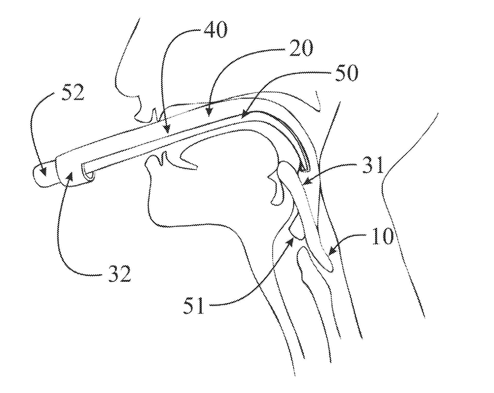
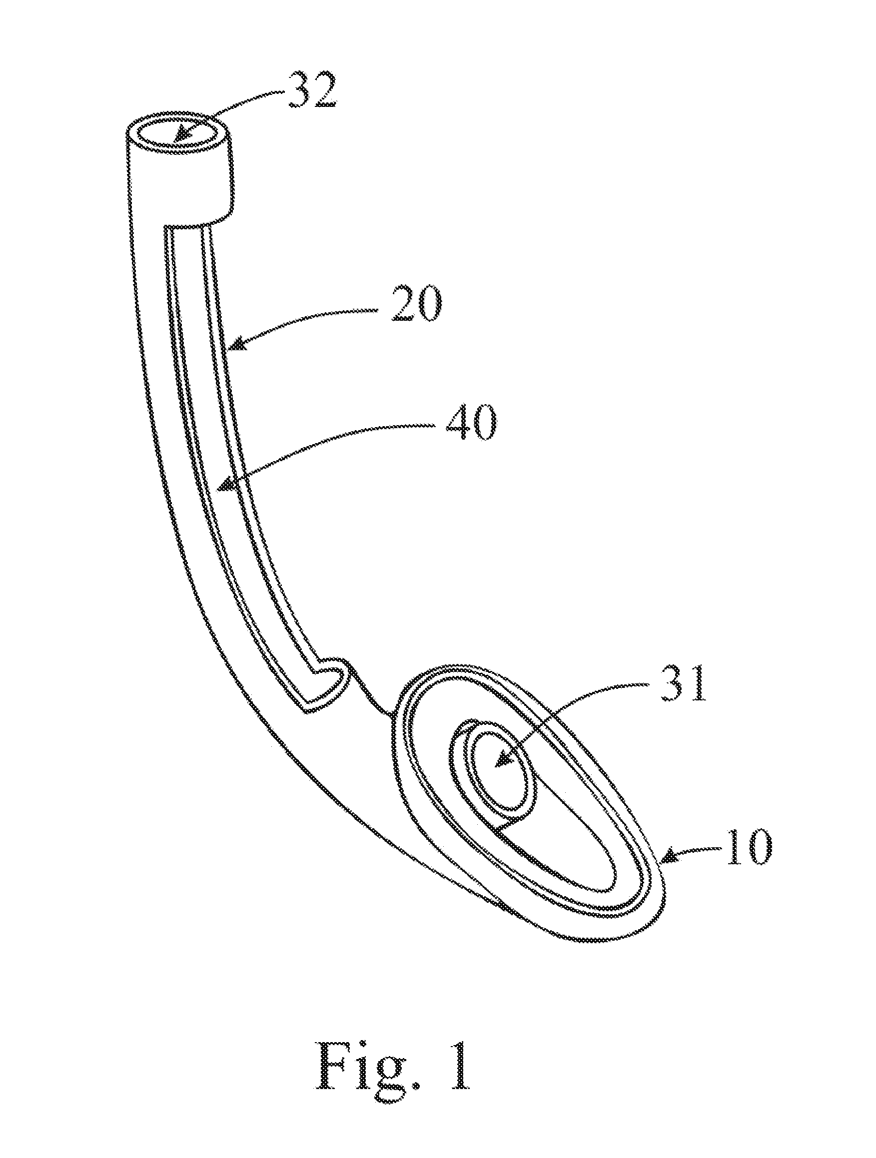
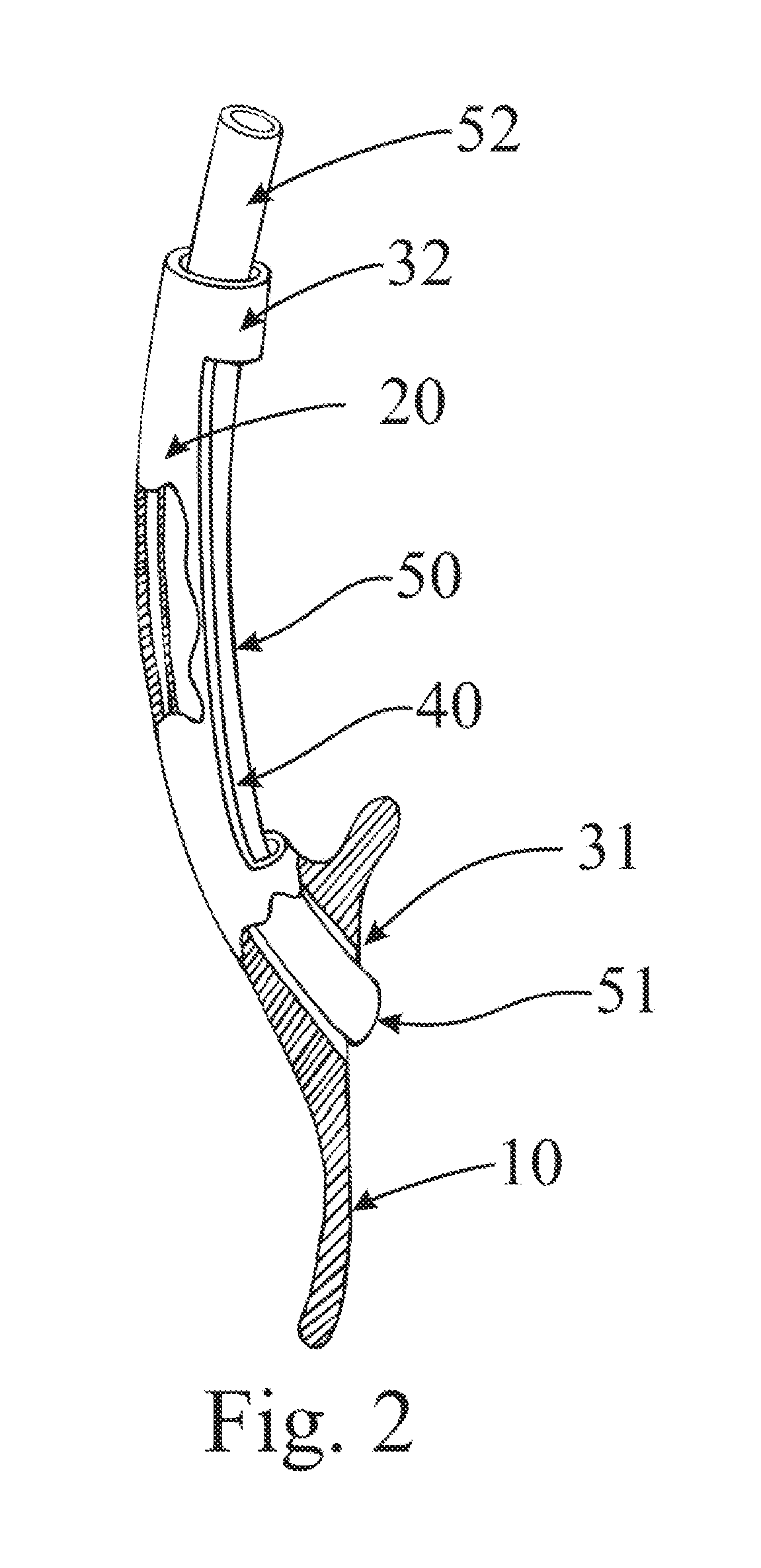
[0034]With reference to FIGS. 1 and 2, an insertion device for endotracheal tubes comprises an anatomically shaped stopper (10), a longitudinal portion (20), a distal annulus (31), a proximal annulus (32), and means (40) to facilitate access to an endotracheal tube positioned between the annuli (31 and 32). It is understood that the anatomically shaped stopper (10) may be an inflatable feature, similar to present laryngeal masks, or alternately an appropriately designed feature made of elastomeric material or similar. FIG. 2 further demonstrates the position of the endotracheal tube (50) within the insertion device. The endotracheal tube (50) has a distal end (51) and proximal end (52). While the endotracheal tube (50) is shown without the usual inflatable cuff, it is to be understood that the preferred embodiment the endotracheal tube will include the inflatable cuff.

[0035]The longitudinal portion (20) is preferably flexible, with it understood that the degree of flexibility dictat...


PUM


Abstract

A device is presented to aid in endotracheal intubation which eases insertion of the endotracheal tube. The insertion device is preferably pre-assembled with a standard endotracheal tube, and the assembly is inserted into the patient's airway, stopping at the esophagus. The endotracheal tube is then advanced to its usual position, and then the insertion device is removed. Easy removal of the insertion device is facilitated by direct access to the endotracheal tube along the anterior side of the insertion device.

Description

REFERENCES CITED[0001]U.S. PATENT DOCUMENTS4,509,514April 1985Bain5,174,283December 1992Paker5,339,805August 1994Paker6,079,409June 2000Bain7,174,889June 2004Boedeker et al.OTHER PUBLICATIONS[0002]Hussain and Redmond, Are pre-hospital deaths from accidental injury preventable?, B M J 1994; 308: 1077[0003]Gerstein et al. Lingual Ischemia from Prolonged Insertion of a Fastrach Laryngeal Mask Airway, The Western Journal of Emergency Medicine, 2011 February; 12(1): 124-127[0004]Eastridge et al. Death on the battlefield (2001-2011): Implications for the future of combat casualty care, Journal of Trauma and Acute Care Surgery: December 2012, Volume 73, Issue 6 p S431-S437.[0005]Young, The intubating laryngeal-mask airway may be an ideal device for airway control in the rural trauma patient, Am Journal of Emergency Medecine, 2003 January; 21(1):80-5BACKGROUND OF THE INVENTION[0006]In medical practice, it is often necessary to secure the airway of a patient. A 1994 study by Hussain and Redm...

Claims


Application Information

Patent Timeline
Patent Type & Authority Applications(United States)
IPC IPC(8): A61M16/04
CPCA61M16/0497A61M2209/06A61M16/0434A61M16/0488A61M16/0409
Inventor KOZLOWSKI, CATHERINE SUSAN
Owner KOZLOWSKI CATHERINE SUSAN
Learn More