3D printing

a technology of 3d printing and printing equipment, applied in the direction of additive manufacturing process, manufacturing tools, layer means, etc., can solve the problem of imperfections on the surface of the produced articl

Active Publication Date: 2015-06-18
IBM CORP
View PDF21 Cites 27 Cited by
  • Summary
  • Abstract
  • Description
  • Claims
  • Application Information

AI Technical Summary

Benefits of technology

[0021]Preferably, in the surface portion modification apparatus, the follower assembly comprises an electromagnetic radiation generator for inducing flow in at least a portion of the object surface by the heating effect of radiation generated thereby. Advantageously, this allows an alternative to the use of a gas or vapor which require arrangements for handling and delivery.
[0022]Preferably, in the surface portion modification apparatus, the electromagnetic radiation generator comprises a laser. Advantageously, this allows the delivery of a heating effect precisely to a desired portion of the object surface.

Problems solved by technology

A problem with the method of deposition described above is that the surfaces of articles produced show imperfections as a result of the method of deposition.

Method used


Image

  • 3D printing
  • 3D printing
  • 3D printing

Examples


Embodiment Construction

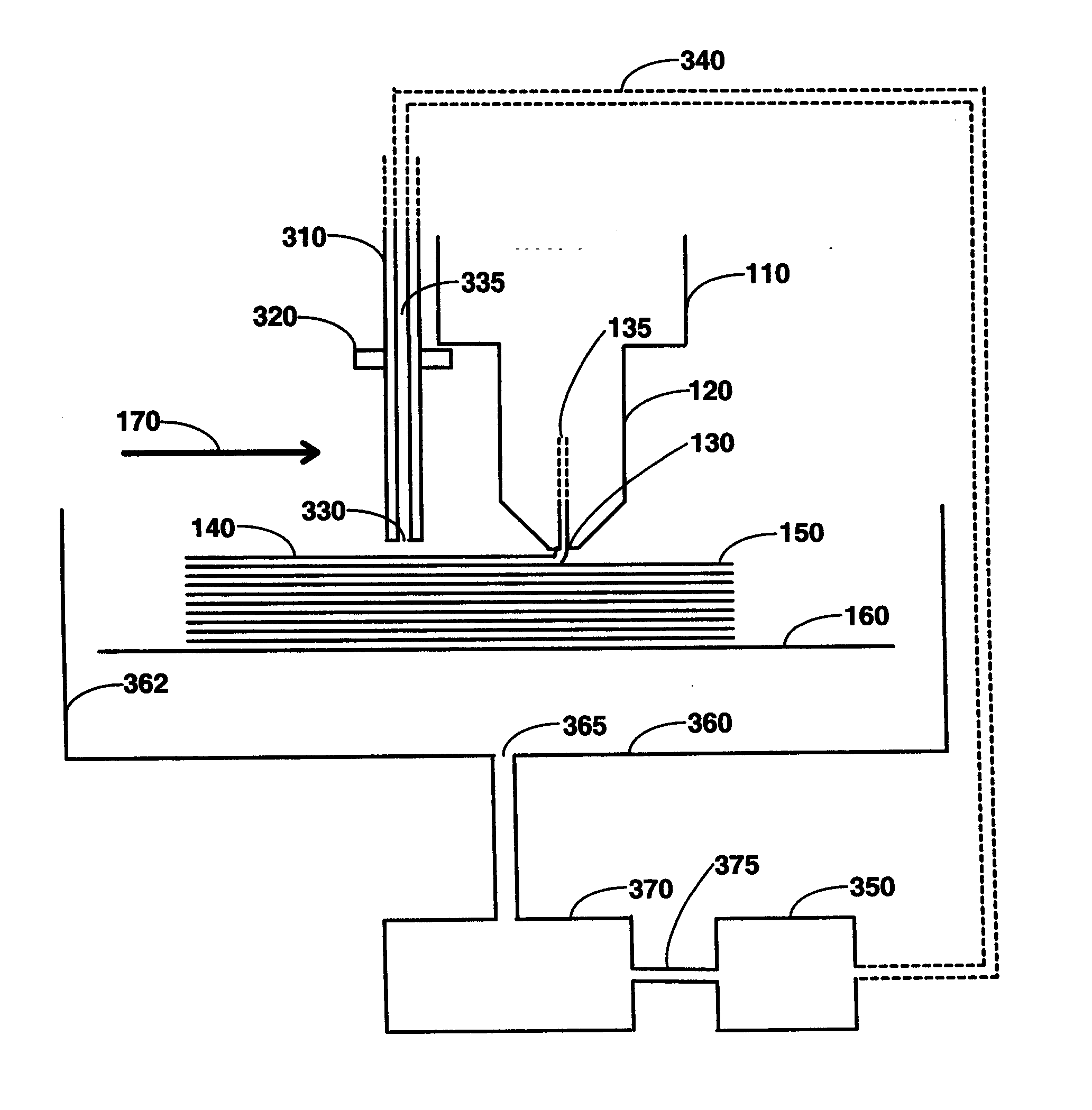
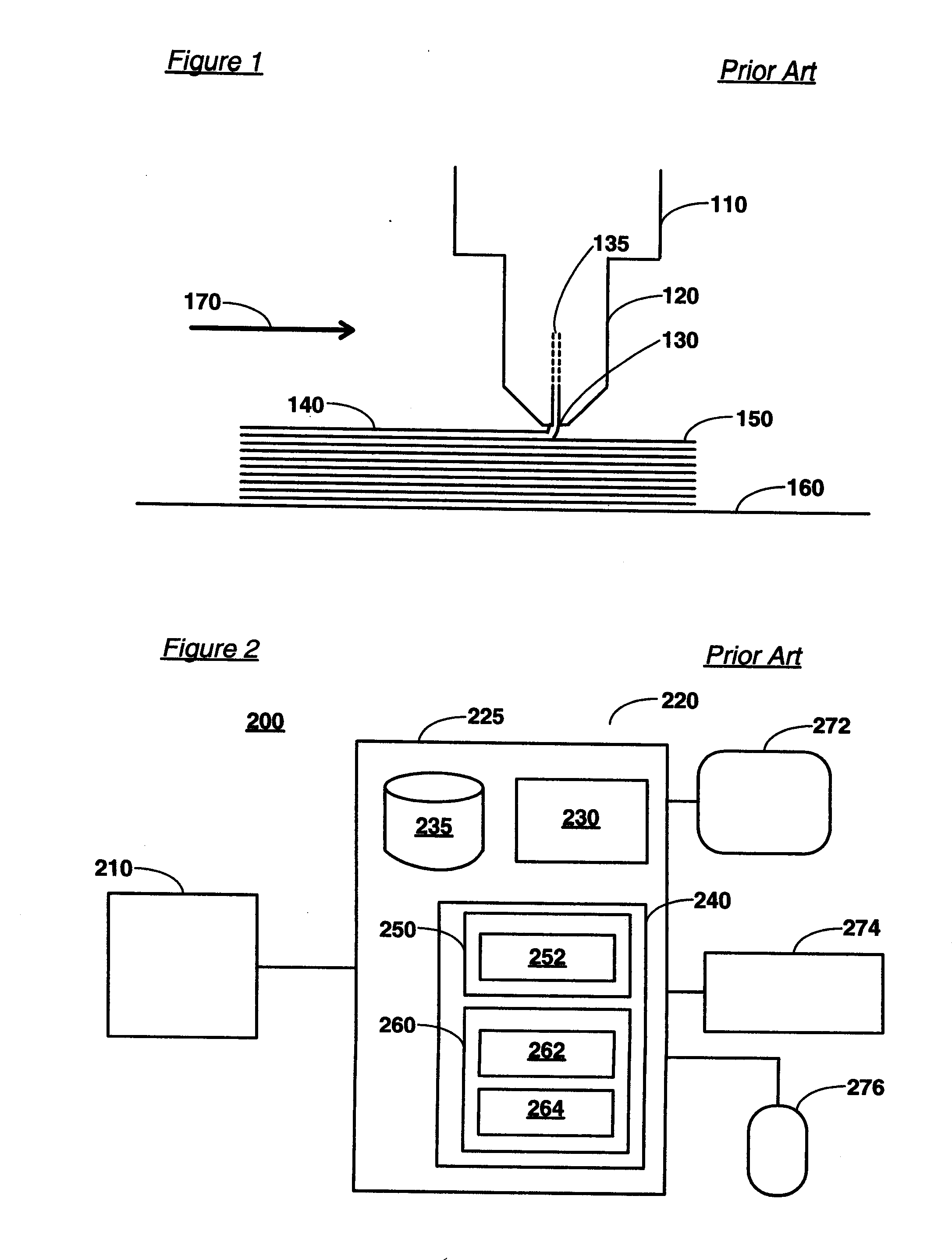
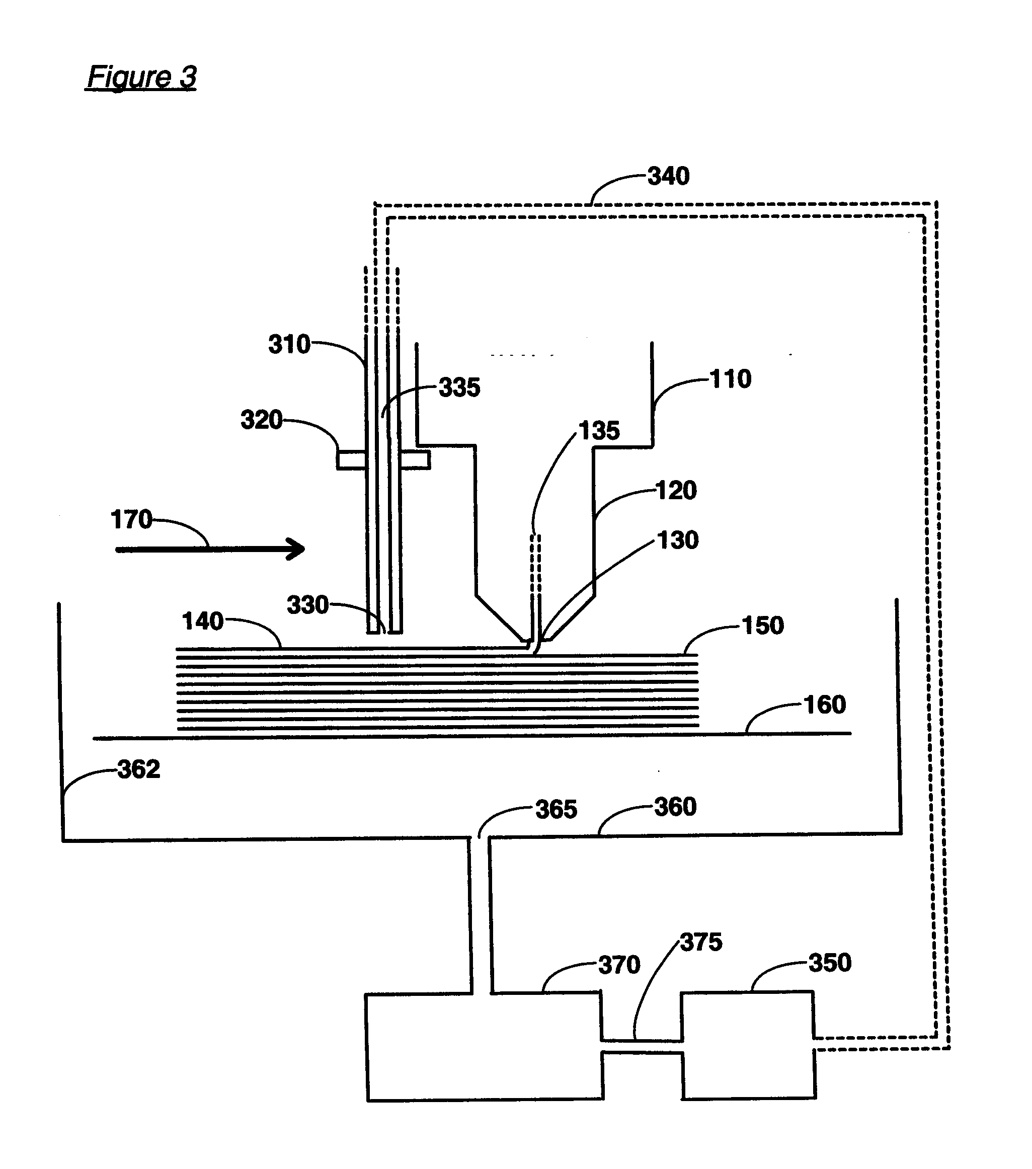
[0049]FIG. 1 illustrates the operation of a 3D printer of the prior art. It is a simplified diagrammatic cross section of a 3D printer, more particularly the printer head, to show the method of operation, and is not intended to show all the elements of such a 3D printer and nor is it necessarily drawn to scale. An exemplary 3D printer according to the prior art comprises printer head assembly 110 and object support base 160 on to which the printer head prints the object to be printed. Head assembly 110 and base 160 are moveable relative to each other in the X, Y and Z directions, where X and Y are the axes of movement in the horizontal plane and Z the axis in the vertical direction upwards relative to base 160. In some embodiments, the base 160 remains stationary, and the head assembly 110 is moved by suitably mounted and controlled electric motors (not shown) either directly or via a movement transfer mechanism, for example via drive belts, so as to build up an object of a required...


PUM

PropertyMeasurementUnit
diameteraaaaaaaaaa
diameteraaaaaaaaaa
diameteraaaaaaaaaa

Abstract

A surface portion modification apparatus is provided which is co-operable with a 3D printer. It includes a head nozzle follower assembly. The follower assembly is co-operable with a 3D printer head nozzle assembly and is operable for modifying at least a portion of a surface of the material of a 3D object printed by the head nozzle assembly of the 3D printer. It may be used to smooth the surface of an object printed by the 3D printer.

Description

FIELD OF THE INVENTION[0001]The invention relates to a 3D printing apparatus. More particularly, the invention relates to improvements to a 3D printing apparatus producing a modified surface of articles produced by the apparatus.BACKGROUND[0002]3D printing is the term used for a process of making a three-dimensional solid object by the laying down of successive layers of an extrudable and settable material from a moving dispenser. The first examples of apparatus performing a process meeting this description were produced in the nineteen eighties.[0003]An example of such an apparatus is described in European patent number EP0833237. This describes an apparatus which incorporates a movable dispensing head provided with a supply of material which solidifies at a predetermined temperature, and a base member, which are moved relative to each other along “X”, “Y,” and “Z” axes in a predetermined pattern to create three-dimensional objects by building up material discharged from the dispen...

Claims


Application Information

Patent Timeline
Patent Type & Authority Applications(United States)
IPC IPC(8): B29C67/00B23K26/00
CPCB33Y10/00B33Y30/00B33Y50/02B29C67/0088B23K26/0036B23K26/0081B29C67/0055B23K26/354B29C64/106B29C64/118B29C64/393B29C64/20B29C64/205B29C64/209B29C64/214B29C64/307B29C64/343
Inventor DAWSON, ALAN B.HUTCHISON, GORDON D.
Owner IBM CORP
Why Eureka
Try Eureka