Open web composite shear connector construction

Active Publication Date: 2015-06-18
URBANTECH CONSULTING ENG PC
View PDF30 Cites 10 Cited by
  • Summary
  • Abstract
  • Description
  • Claims
  • Application Information

AI Technical Summary

Benefits of technology

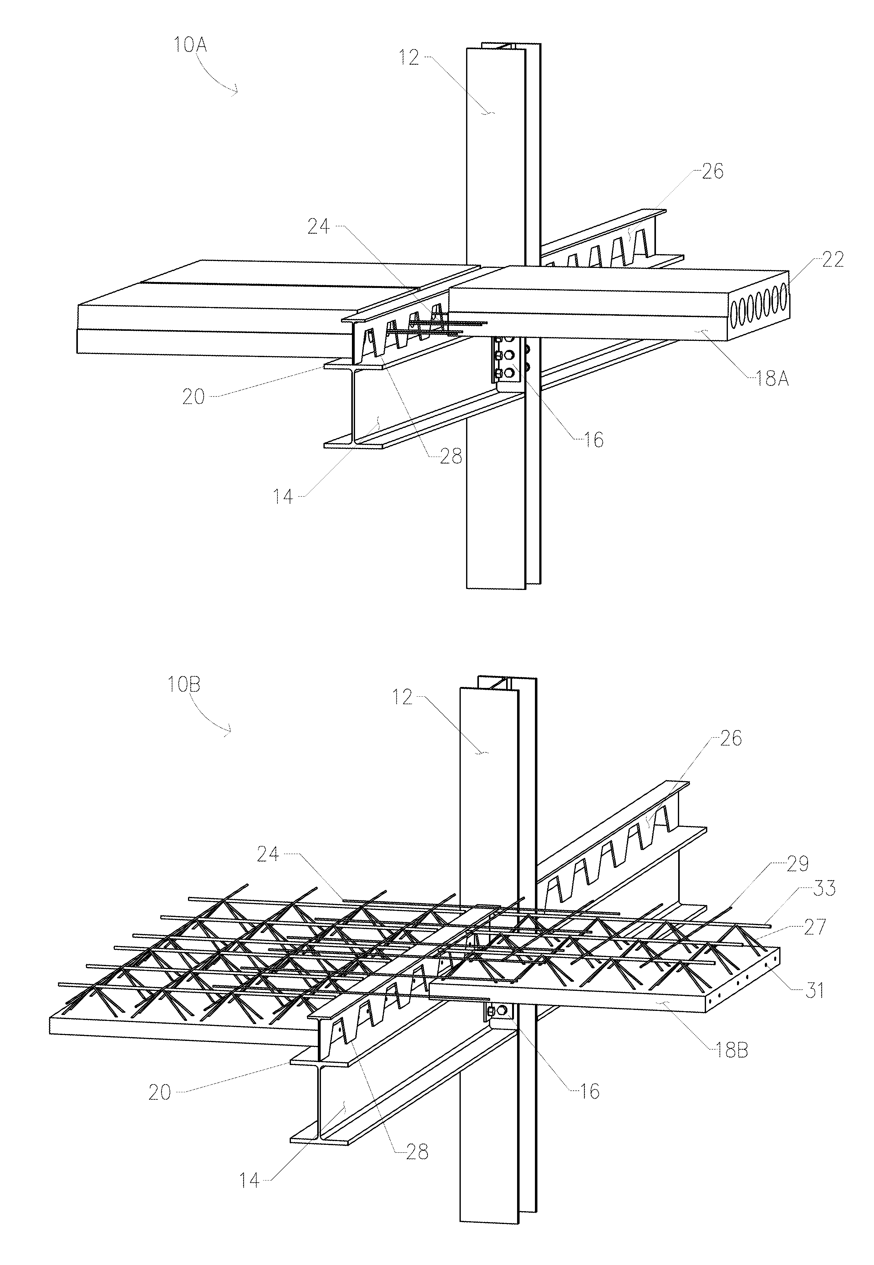
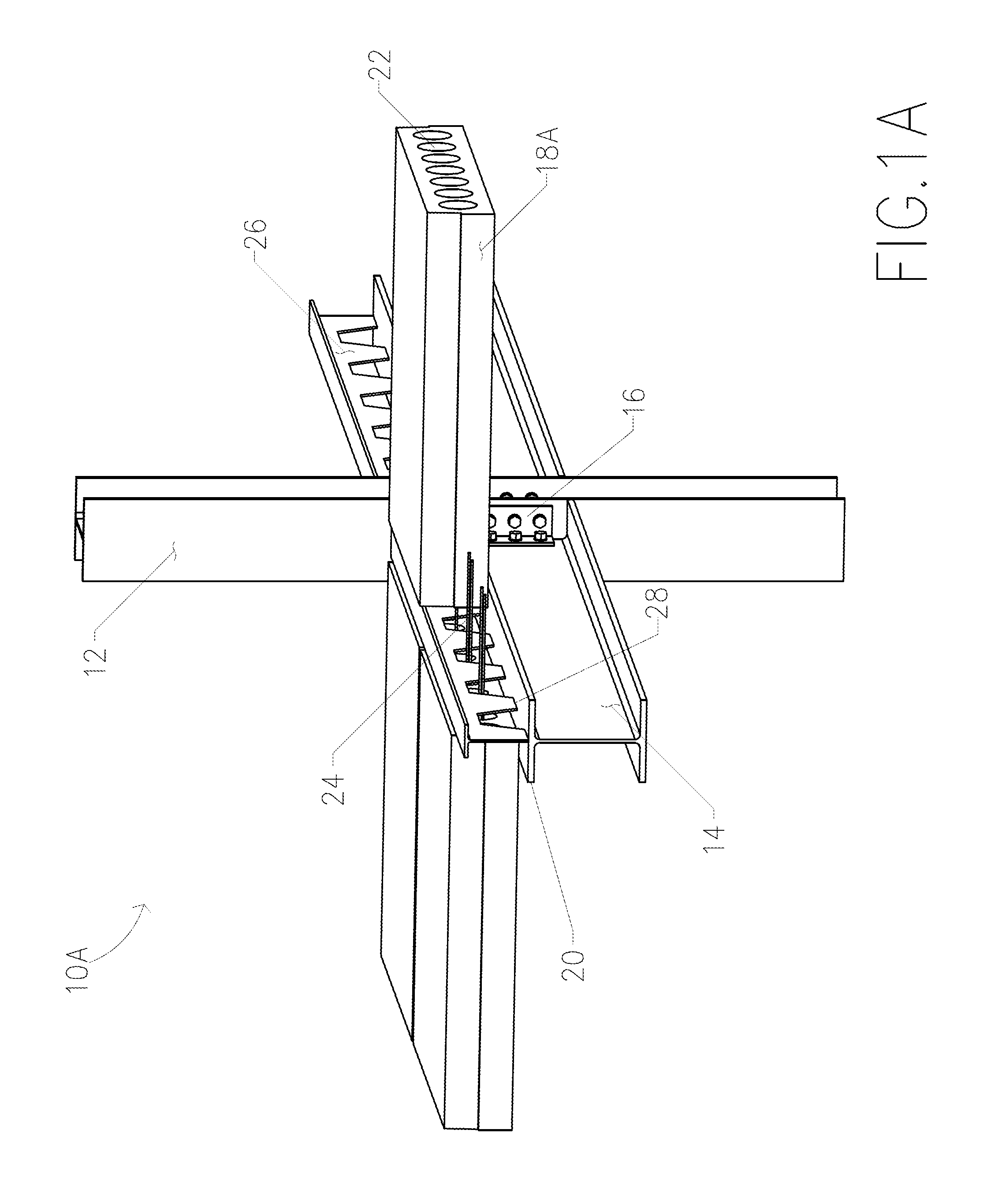
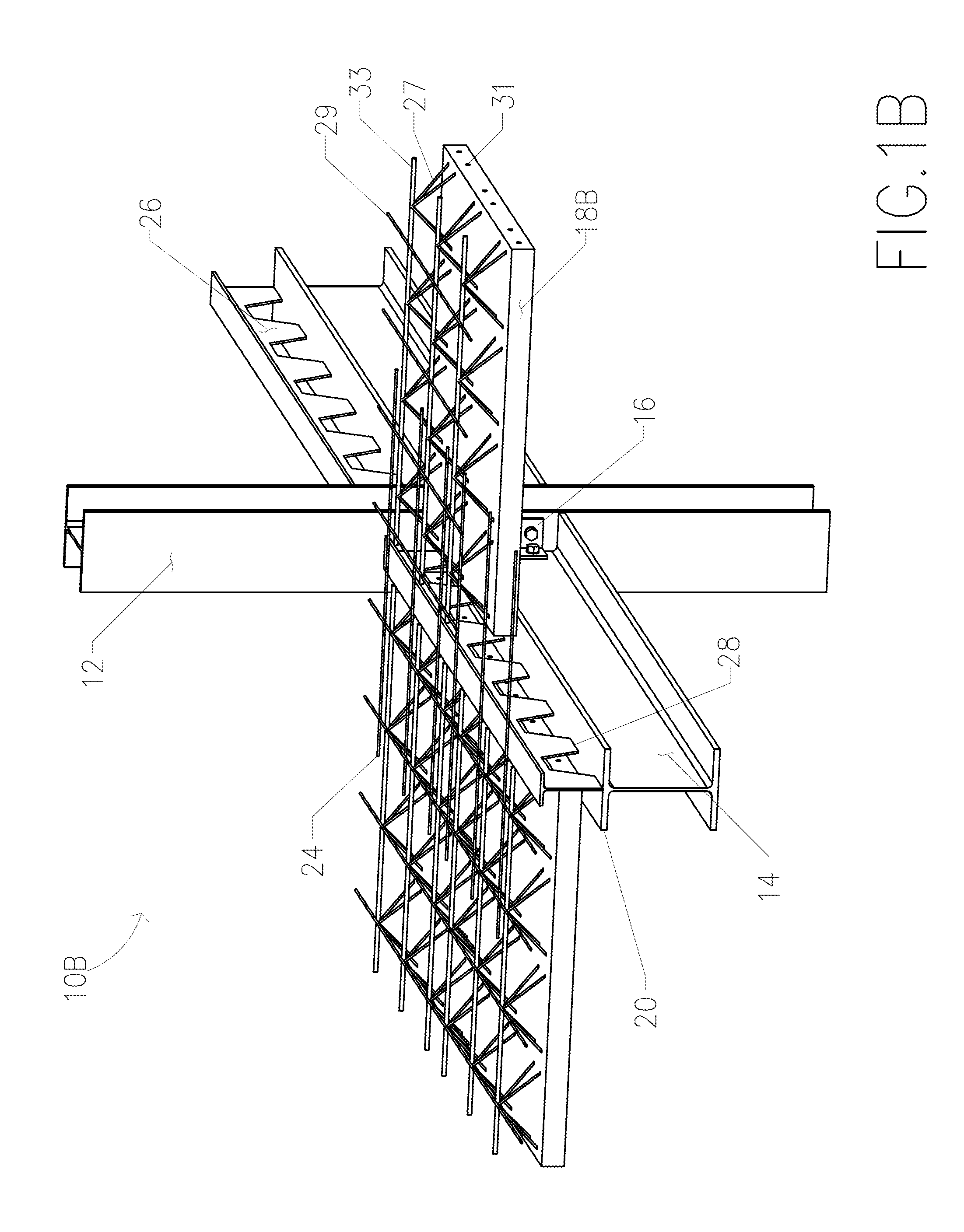
This patent describes a framing system for building structures using vertical columns and a base beam section. The system also includes concrete plank sections that are supported by the base beam and can be assembled in pairs. Grout material is used to fill the cavities of the assembly and increase strength. The technical effect of this patent is to provide a stronger and more stable framing system for building structures.

Problems solved by technology

One problem associated with structures built from the precast concrete components is the overall integrity.
However, there are other integrity problems left unanswered.
Currently, technologies for integrating these two types of materials are underdeveloped, which, as a result, inevitably hinders constructions based on these types of materials.

Method used


Image

  • Open web composite shear connector construction
  • Open web composite shear connector construction
  • Open web composite shear connector construction

Examples


second embodiment

[0031]FIG. 3 shows a cross-sectional view of a structural framing system 310. In some embodiments, the base beam section 314 can be steel plate or the like. The rest of the construction can be similar to system 10A, with concrete planks 318, passages 322, reinforcement bar 324, concrete fill 330, dam 332, and concrete overlay 334. Joint 328 can be similar to the joint 28, discussed above, and used to connect shear connector 326 to steel plate 314.

third embodiment

[0032]FIG. 4 shows a cross-sectional view of a structural framing system 410. In some embodiments, the base beam section 414 can comprise one or more steel channels, which can be welded, or otherwise joined, to either side of shear connector 426. In this configuration, the rest of the construction can be similar to system 10A, with concrete planks 418, passages 422, reinforcement bar 424, concrete fill 430, dam 432, and concrete overlay 434. Joint 428 can be similar to the joint 28, discussed above, and used to connect shear connector 426 to beam section 414.

fourth embodiment

[0033]FIG. 5 shows a cross-sectional view of a structural framing system 510. In this configuration, the base beam section 514 can comprise one or more steel channels bolted to either side of shear connector 526 with bolts 536, rivets, welds, or otherwise suitably joined. The rest of the construction can be similar to system 10A, with concrete planks 518, passages 522, reinforcement bar 524, concrete fill 530, dam 532, and concrete overlay 534.


PUM


Abstract

A system for constructing multi-story building is disclosed. The system can include a plurality of vertical beams and a base beam section. The base beam section can be supported horizontally between the plurality of vertical column members and can include a composite shear connector attached thereto. The framing system can further include a plurality of concrete plank sections spanning perpendicularly to, and supported by, either side of the base beam. The plurality of concrete plank sections can be assembled in pairs. The framing system can also include grout material applied to the composite shear connector and the concrete plank sections to fill the cavities of the assembly to provide an integral framing system. A method for assembling such a system is also disclosed.

Description

CROSS-REFERENCE TO RELATED APPLICATIONS[0001]This application claims the benefit of U.S. Provisional Patent Application Ser. No. 61 / 915,840, entitled “Open Web Composite Shear Connector Construction,” filed on Dec. 13, 2013, which is incorporated herein by reference in its entirety as if fully set forth below.TECHNICAL FIELD[0002]Embodiments of the present technology relate to the construction of multi-story buildings, and more particularly to an improved structural framing system and associated method for construction of such buildings. The system comprises a composite concrete and steel assembly, which can incorporate one or more steel beams disposed between, and joined along, adjacent edges of precast concrete plank members such that the composite strength of the structure is substantially enhanced.BACKGROUND OF RELATED ART[0003]When constructing a multi-story building, the framing system is generally the load bearing structure that supports the building. Commercial framing, for ...

Claims


Application Information

Patent Timeline
IPC IPC(8): E04B1/19E04B1/98E04H9/02E04B1/24E04H1/04
CPCE04B1/1903E04B1/24E04B1/98E04H9/02E04H1/04E04B5/043E04B5/29E04B5/38E04B2001/2466E04B2001/2484E04H9/024
Inventor WANG, WEI
Owner URBANTECH CONSULTING ENG PC
Why Eureka
Try Eureka