Heat treatment device for optical fiber reinforcing member, optical fiber fusion splicer provided with same heat treatment device, and method for heat treating optical fiber reinforcing member

a technology of heat treatment device and heating temperature, which is applied in the direction of optics, optical light guides, instruments, etc., can solve the problems of increasing the amount of power consumed by the heater, reducing the amount of heat generated by the heater per unit time, and increasing the time to reach a desired heating temperature. , to achieve the effect of optimizing the heating condition

Active Publication Date: 2015-06-18
SEI OPTIFRONTIER CO LTD
View PDF7 Cites 5 Cited by
  • Summary
  • Abstract
  • Description
  • Claims
  • Application Information

AI Technical Summary

Benefits of technology

[0010]In the present invention, the heater is heated on the basis of a heating condition selected from a plurality of different heating conditions in accordance with a value of the parameter obtained from the detecting unit. Therefore, it is possible to optimize the heating condition for the reinforcing member in accordance with various parameters, including a voltage applied to the heating device.

Problems solved by technology

However, using a planar heating element reduces the amount of heat generated by the heater per unit time and increases the time to reach a desired heating temperature.
This results in an increase in the amount of power consumed by the heater to heat one reinforcing member.
If the heater is supplied with power from a battery, the battery may be exhausted before completion of the heating process.

Method used


Image

  • Heat treatment device for optical fiber reinforcing member, optical fiber fusion splicer provided with same heat treatment device, and method for heat treating optical fiber reinforcing member
  • Heat treatment device for optical fiber reinforcing member, optical fiber fusion splicer provided with same heat treatment device, and method for heat treating optical fiber reinforcing member
  • Heat treatment device for optical fiber reinforcing member, optical fiber fusion splicer provided with same heat treatment device, and method for heat treating optical fiber reinforcing member

Examples


example 1

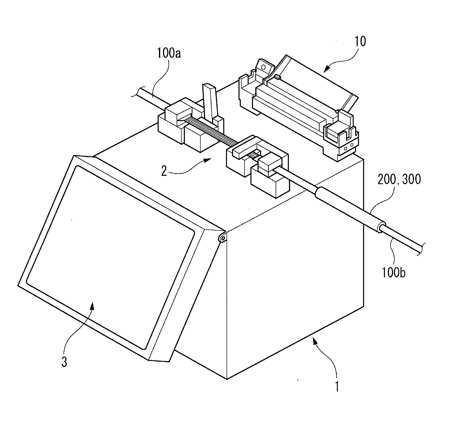
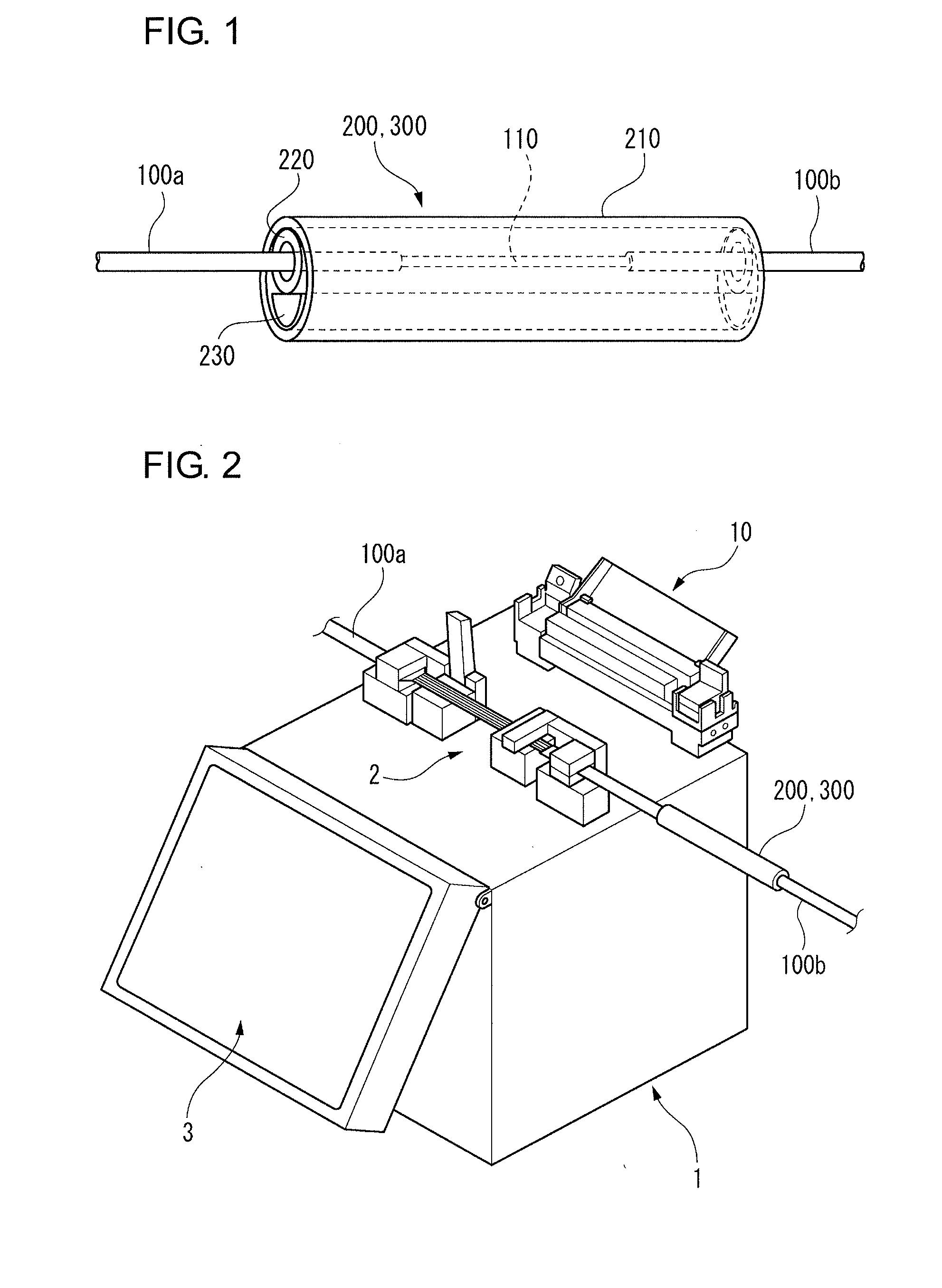
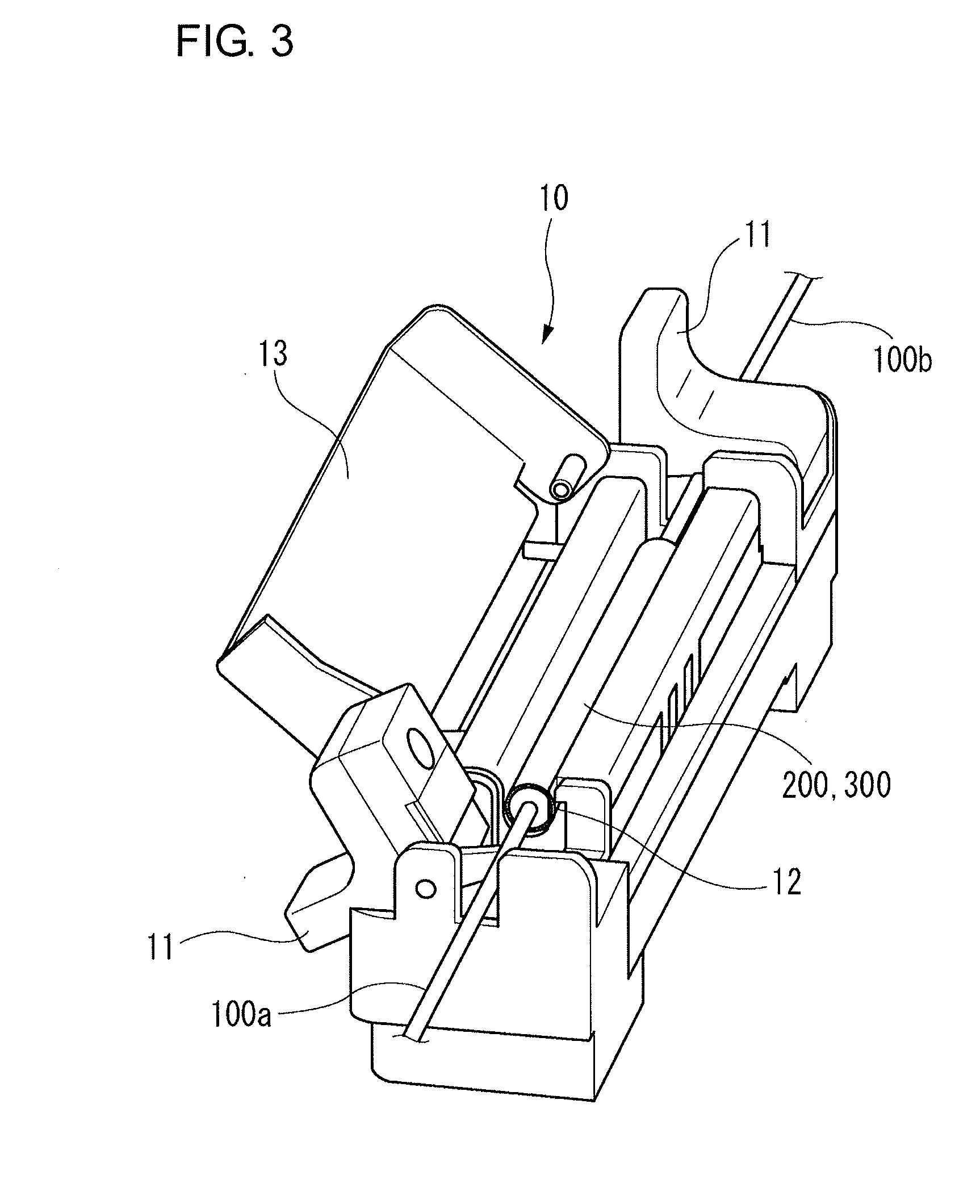
[0040]Table I shows a result of examples where the reinforcing member 200 covering the fusion-spliced portion 110 was heated and shrunk by the heating device 10.

TABLE IHeating conditionsHeatingNaturalForcibleTctcTstscoolingcoolingV(V)(° C.)(s)(° C.)(s)tn (s)tf (s)tr (s)Compar-13.8230523013529.15ative11.838.12example 111.047.910.079.069.097.28Example 113.82305230130529.1511.823023038.1211.021521535.410.020020036.169.018518538.029.016016088041.95 to47.19

[0041]In comparative example 1, although a voltage V applied to the heating device 10 was varied from 9 V to 13.8 V, the optimization of the heating condition for heating the heater 12 (including a heating temperature Tc for heating a central portion, a voltage application period tc for applying a voltage to the central portion after the temperature Tc was reached, a heating temperature Ts for heating both end portions, a voltage application period ts for applying a voltage to both the end portions after the temperature Ts was reached,...

example 2

[0044]Next, an evaluation test similar to that for the reinforcing member 200 was performed using the fusion-spliced portion 110 covered with a reinforcing member 300. The reinforcing member 300 has dimensions different from those of the reinforcing member 20. The test result is shown in Table II.

TABLE IIHeating conditionsHeatingNaturalForcibleTctcTstscoolingcoolingV(V)(° C.)(s)(° C.)(s)tn (s)tf (s)tr (s)Compar-13.82301221013533.41ative11.838.47example 211.045.9310.065.119.085.94Example 213.823012210130533.411.8230122101338.4711.0225132051444.4610.0215142001551.449.0205151951663.08

[0045]In comparative example 2, although the supply voltage of a battery connected to the heating device 10 was varied from 9 V to 13.8 V as in comparative example 1, the heating condition for the reinforcing member 300 was the same regardless of the voltage. As a result, in comparative example 2, the heating and reinforcing period significantly increased as the supply voltage of the battery decreased, as ...

example 3

[0047]An evaluation test was performed to examine the relationship between the number of heating operations and the level of battery drain when the fusion-spliced portion 110 covered with the reinforcing member 300 was heated and reinforced by the heating device 10 connected to a low-voltage battery. In comparative example 3, the heating condition previously used (heating temperature Tc: 230° C., heating period tc: 5 seconds, heating temperature Ts: 230° C., heating period ts: 13 seconds, and natural cooling period: 0 seconds) was used. In example 3, an optimum heating condition for the low-voltage battery (heating temperature Tc: 210° C., heating period tc: 5 seconds, heating temperature Ts: 210° C., heating period ts: 8 seconds, and natural cooling period: 5 seconds) was used. Table III shows the result. In Table III, “remaining battery power” indicates the amount of remaining power in percentage relative to the power of the battery in a fully charged state.

TABLE IIIRemaining batt...


PUM


Abstract

A heating device for heating an optical fiber reinforcing member includes fiber holders to hold optical fibers covered with the reinforcing member at a fusion-spliced portion, a heater to heat the reinforcing member, a power supply unit to apply a voltage to the heater, and a controller to control the application of a voltage from the power supply unit to the heater. The controller includes a detecting unit that detects a parameter for determining the amount of heat generation of the heater, a storage unit that stores a plurality of heating conditions that vary depending on the parameter value, and a condition instruction unit that selects any of the plurality of heating conditions in accordance with the parameter value detected by the detecting unit and instructs the power supply unit to apply a voltage to the heater on the basis of the selected heating condition.

Description

TECHNICAL FIELD[0001]The present invention relates to a heating device for an optical fiber reinforcing member, an optical fiber fusion splicer including the heating device, and a method for heating the optical fiber reinforcing member. The heating device heats and shrinks the reinforcing member protecting a fusion-spliced portion of optical fibers to reinforce the fusion-spliced portion.BACKGROUND ART[0002]Japanese Patent No. 4164375 describes a heating device that heats and shrinks a reinforcing member protecting a fusion-spliced portion of optical fibers to reinforce the fusion-spliced portion. The heating device includes a heating unit (heater) formed by a planar heating element which is bent to have a substantially U-shaped cross section. The planar heating element has a central heating portion which is a U-shaped bottom portion in surface contact with the reinforcing member held therein, and side heating portions which are both side portions not in contact with the reinforcing...

Claims


Application Information

Patent Timeline
Patent Type & Authority Applications(United States)
IPC IPC(8): G02B6/255
CPCG02B6/2558G02B6/2551
Inventor FUKUDA, MASAKAZUITO, KENSUKE
Owner SEI OPTIFRONTIER CO LTD
Why Eureka
Try Eureka