
Regenerative combustion V2O5 melting furnace

A V2O5, regenerative technology, applied in the field of metallurgy, can solve the problems of large exhaust heat loss, poor production environment, high equipment cost, etc., and achieve the effect of improving heating conditions, increasing heating speed, increasing product quality and output

Inactive Publication Date: 2018-06-05
NORTHEASTERN UNIV +1
View PDF6 Cites 0 Cited by
  • Summary
  • Abstract
  • Description
  • Claims
  • Application Information

AI Technical Summary

Problems solved by technology

The "one-step" production method of vanadium pentoxide is the process of dehydrating, decomposing, and melting wet ammonium vanadate in a melting furnace. The "one-step" production method has low energy utilization rate, large heat loss from exhaust smoke, and poor production environment. , the disadvantage of large pollution
The "three-step" production method of vanadium pentoxide refers to the process of dehydration, decomposition and melting in three different equipment. Although the "three-step" production method solves the problem of energy utilization, However, the equipment cost is high, the structure is complicated, it is not suitable for small-scale production, and it is difficult to be accepted by most enterprises.

Method used


Image

  • Regenerative combustion V2O5 melting furnace
  • Regenerative combustion V2O5 melting furnace
  • Regenerative combustion V2O5 melting furnace

Examples


Embodiment 1

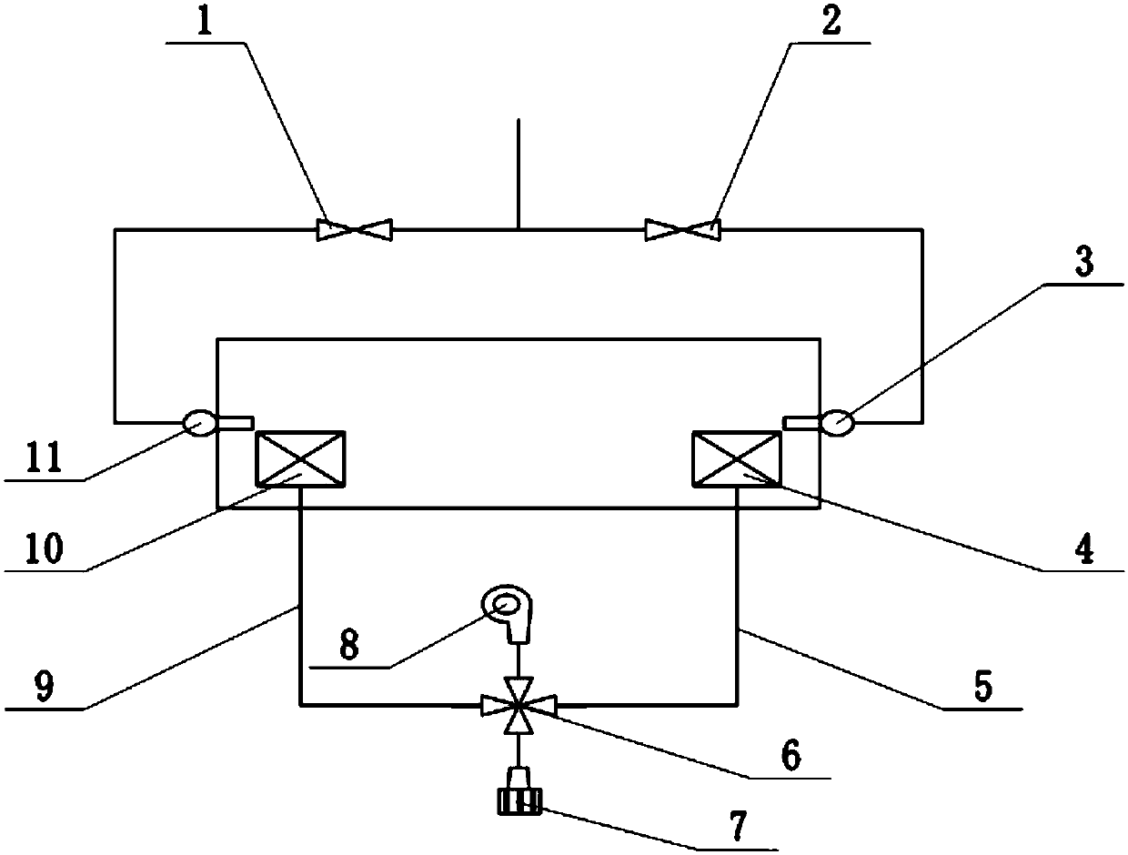
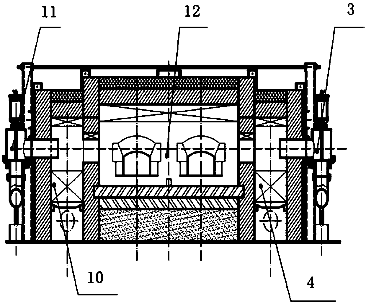
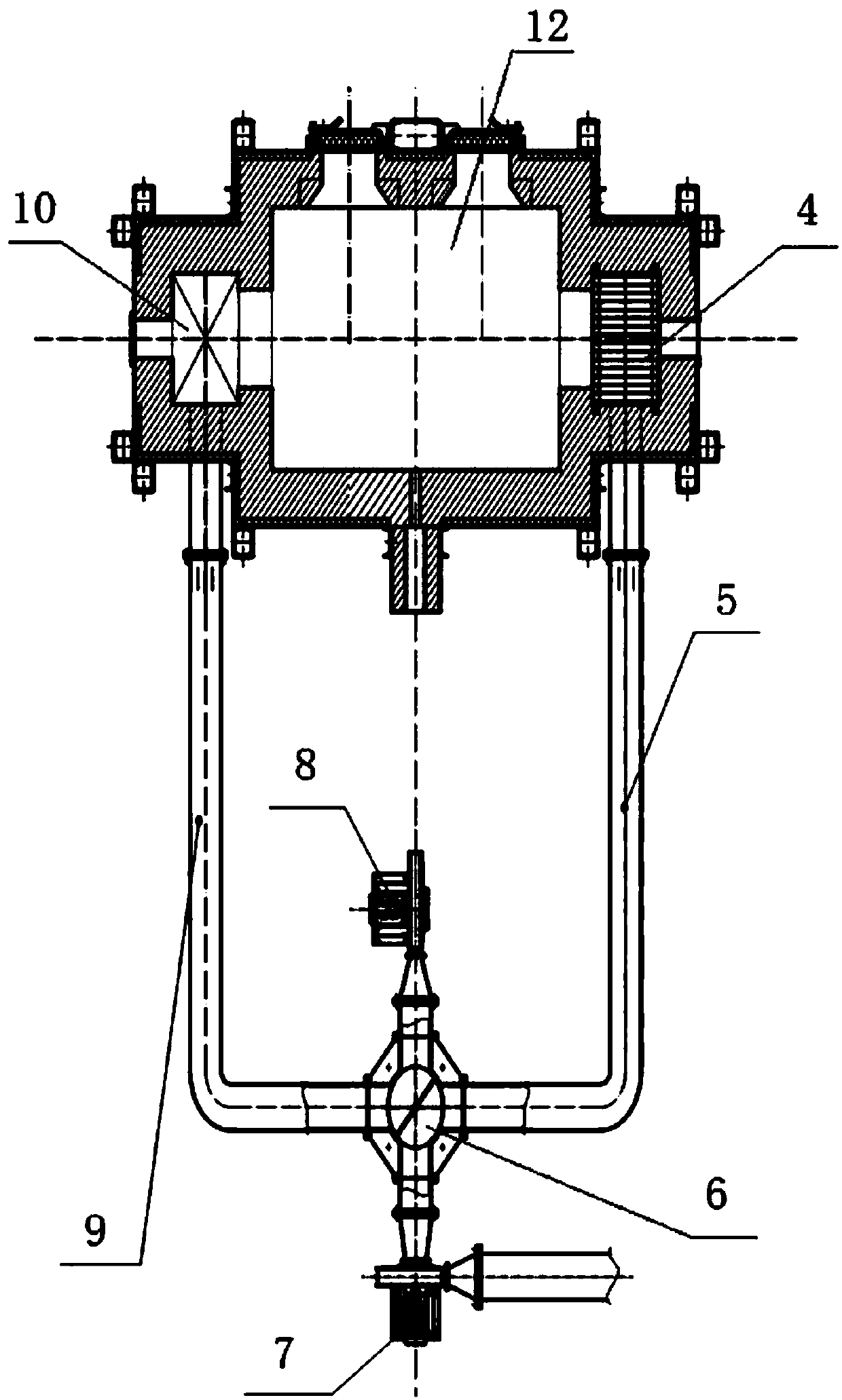
[0019] Such as Figure 1-3 As shown, a regenerative combustion V 2 o 5 Melting furnace, including melting furnace body 12, regenerative air heat exchange device A10, regenerative air heat exchange device B4, burner A11, burner B3, air-flue gas pipeline A9, air-flue gas pipeline B5, electric control multi-directional valve, induced draft fan 7 and blower 8, the melting furnace body 12 adopts a chamber-shaped furnace structure, the furnace roof adopts a 60° vault, and is filled with aluminum silicate fibers with good thermal insulation properties, and the furnace wall is piled up with refractory clay bricks. Aluminum silicate fibers are laid on the outside for heat preservation, and the outermost layer is supported by steel plates; the regenerative air heat exchange device A10 and the regenerative air heat exchange device B4 are respectively installed on both sides of the melting furnace body 12, and the burner A11 is installed on the regenerative air heat exchange device A10,...

Embodiment 2

[0025] Such as Figure 4 As shown, the difference from Embodiment 1 is that the electronically controlled multi-directional valve is an electronically controlled combined valve 13, through the opening and closing of different valves, the direction of gas flow is changed, and the rapid conversion of incoming gas and exhaust gas is realized.


PUM


Abstract

The invention belongs to the field of metallurgy, and particularly relates to a regenerative combustion V2O5 melting furnace. The technical scheme includes that the melting furnace comprises a meltingfurnace body, a regenerative air heat exchanging device A, a regenerative air heat exchanging device B, a combustor A, a combustor B, an air-flue gas pipeline A, an air-flue gas pipeline B, an electric control multi-directional valve, an induced draft fan and a supply fan, the regenerative air heat exchanging device A and the regenerative air heat exchanging device B are mounted on two sides of the melting furnace body, the combustor A is mounted on the regenerative air heat exchanging device A, the combustor B is mounted on the regenerative air heat exchanging device B, one end of the air-flue gas pipeline A is connected with the regenerative air heat exchanging device A, one end of the air-flue gas pipeline B is connected with the regenerative air heat exchanging device B, and the otherends of the air-flue gas pipeline A and the air-flue gas pipeline B, the induced draft fan and the supply fan are integrally connected with the electric control multi-directional valve. According tothe melting furnace, combustion-supporting air is preheated by the aid of high-temperature flue gas, and the heat efficiency of the furnace is improved.

Description

technical field [0001] The invention belongs to the field of metallurgy, in particular to a regenerative combustion V 2 o 5 melting furnace. Background technique [0002] Vanadium is an important strategic resource in my country, mainly used in metallurgy, chemical industry, national defense industry, aerospace and other fields. At present, the main methods used in the melting of vanadium pentoxide in my country are "one-step method" and "three-step method" production methods. The "one-step" production method of vanadium pentoxide is the process of dehydrating, decomposing, and melting wet ammonium vanadate in a melting furnace. The "one-step" production method has low energy utilization rate, large heat loss from exhaust smoke, and poor production environment. , the disadvantage of large pollution. The "three-step" production method of vanadium pentoxide refers to the process of dehydration, decomposition and melting in three different equipment. Although the "three-ste...

Claims


Application Information

Patent Timeline
IPC IPC(8): F27B14/14F27D17/00F23D14/66
CPCF23D14/66F27B14/14F27B2014/146F27D17/004F27D2017/007F27M2003/13Y02E20/34
Inventor 董辉罗博张井凡高文丰
Owner NORTHEASTERN UNIV
Learn More