
Anomaly detecting method, and apparatus for the same

a technology of anomaly detection and anomaly detection, applied in the direction of instruments, testing/monitoring control systems, nuclear elements, etc., can solve the problems of difficulty in application to any other equipment than what operates regularly, and the problem of taking a long time for calculation, etc., and achieve the effect of high sensitiveness

Active Publication Date: 2015-06-18
HITACHI HIGH-TECH CORP +1
View PDF2 Cites 31 Cited by
  • Summary
  • Abstract
  • Description
  • Claims
  • Application Information

AI Technical Summary

Benefits of technology

The patent describes a system for monitoring the status of equipment. The system includes a computer software program that works with a variety of sensors and other devices to collect data about the equipment's condition. This data is then analyzed to help detect and prevent problems with the equipment. The system can be set up in different configurations to meet different needs, and its goal is to make it easier to monitor and maintain the health of equipment in real-time.

Problems solved by technology

The anomaly detecting method by which the presence or absence of anomaly is detected on the basis of average and variance in each individual period and another anomaly detecting method by which the presence or absence of anomaly is detected on the basis of the number of times of deviation from a single-period waveform model for each feature, both being stated in Patent Document 1, involves the problem of difficulty of application to any other equipment than what operates regularly.
Still another method based on a plurality of normal models generated by random sampling involves the problem of taking a long time for calculation.

Method used


Image

  • Anomaly detecting method, and apparatus for the same
  • Anomaly detecting method, and apparatus for the same
  • Anomaly detecting method, and apparatus for the same

Examples


first embodiment

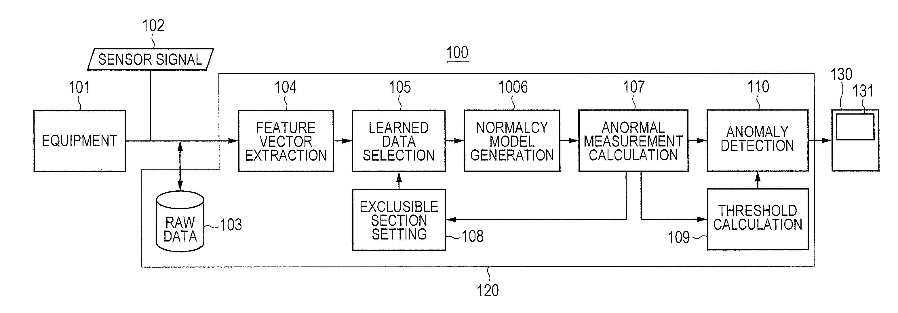
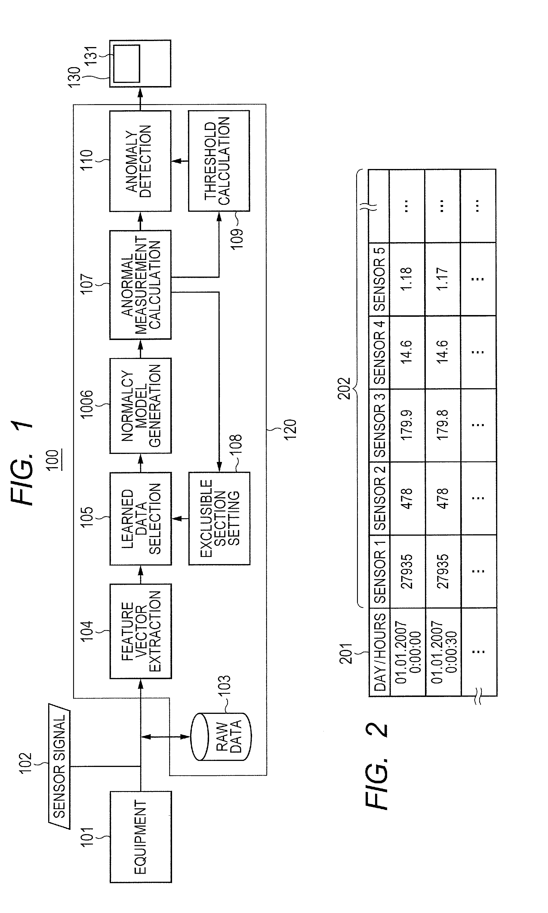
[0040]FIG. 1 shows an example of configuration of an anomaly detection system 100 for realizing the equipment state monitoring method according to the invention.

[0041]This anomaly detection system 100 comprises a sensor signal analyzing unit 120 and an input / output unit 130. The sensor signal analyzing unit 120 further comprises a sensor signal storing unit 103 that accumulates as raw data sensor signals 102 outputted from equipment 101; a feature vector extracting unit 104 that extracts feature vectors on the basis of the sensor signals 102; a learned data selecting unit 105 that excludes feature vectors in learning-excluded periods from the feature vectors of a pre-designated learning period; a normal model generating unit 106 that generates a normal model matching a feature vector matching each of different time points by using the selected learned data; an anomaly measurement calculating unit 107 that sets anomaly measurements on the basis of the feature vectors at different tim...

second embodiment

[0100]This anomaly detection system 100 is provided with a sensor signal analyzing unit 120 and an input / output unit 130.

[0101]While a first embodiment was described with respect to a method of anomaly detection on the basis of sensor signals outputted from equipment, another embodiment to be described now uses a method of anomaly detection that also utilizes event signals outputted from equipment. FIG. 13A shows the configuration of an anomaly detection system 1300 that implements the anomaly detection method of this embodiment. The anomaly detection system 1300 is provided with a sensor signal analyzing unit 1320 and an input / output unit 1330. In the anomaly detection system 1300 in this embodiment, the anomaly detection system 100 of the first embodiment shown in FIG. 1 has a configuration including a mode splitting unit 1302 added to the sensor signal analyzing unit 120. Constituent elements assigned the same reference numbers as in the configuration illustrated by FIG. 1 have r...

third embodiment

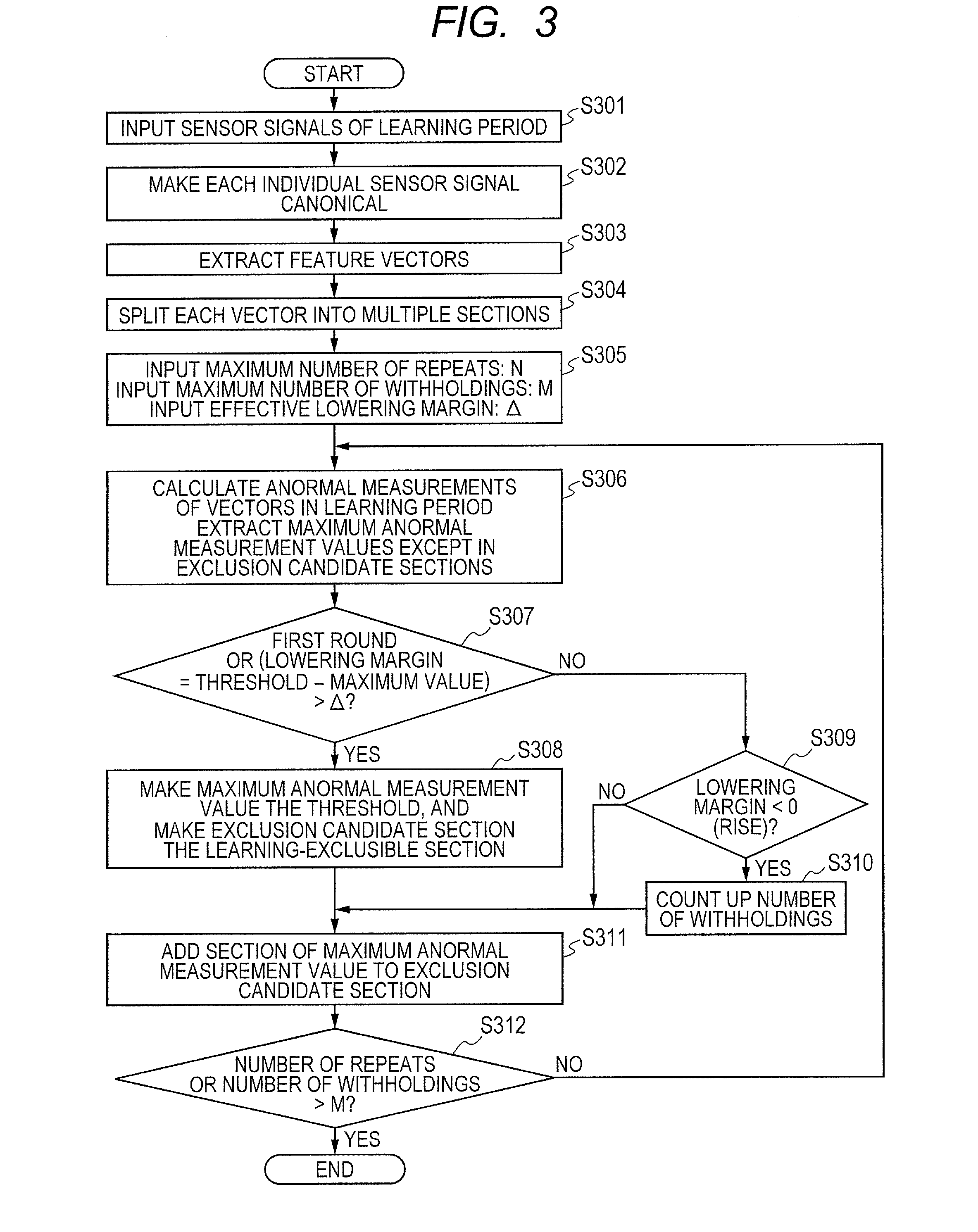
[0117]While learning exclusion periods are determined on the basis of the results of anomaly measurement calculation in the first and second embodiments, in this embodiment user-designated periods of periods satisfying user-designated conditions are initially set as learning exclusion periods. A step to set learning exclusion period is inserted before step S305 at the time of learning described with reference to FIG. 3 or step S605 in FIG. 6 in the first embodiment.

[0118]A method of designating periods by the user may use a dedicated GUI or file inputting. For instance, a numerical value such as “20090726” representing the year, month and day is written in advance on one line. This means Jul. 26, 2009. Of course, designation may as well be done with a period number.

[0119]Examples of user designation of conditions are described below.

[0120]A first example is processing to set learning exclusion period by using event signals. Basically, it is determined on the basis of event signal wh...


PUM


Abstract

In an anomaly detecting method by using multi-dimensional time series sensor signals including, generating anomaly model by using data of a learning period including neither that period nor any exclusion candidate period, calculating anomaly measurements on the basis of the distance from the normal model and, making a period containing the maximum anomaly measurement value but no exclusion candidate period, learning exclusion periods and anomaly determining thresholds are determined as learned data on the basis of the result in each round, generates anomaly model data in a learning period except learning-exclusion periods regarding acquired data or data in a designated evaluation period, an anomaly measurement at each time point is calculated on the basis of the distance from the normal model, and data at each time point is determined to be anomaly or normal by comparing the anomaly measurements with anomaly determining thresholds.

Description

CLAIM OF PRIORITY[0001]The present application claims priority from Japanese Patent Application JP 2013-258215 filed on Dec. 13, 2013, the content of which is hereby incorporated by reference into this application.BACKGROUND OF THE INVENTION[0002]1. Field of the Invention[0003]The present invention relates to an anomaly detecting method and an anomaly detecting apparatus that can accomplish early detection of any anomaly on the basis of multi-dimensional time series data outputted by a plant or facility.[0004]2. Description of the Related Art[0005]Electric power companies are utilizing waste heat from gas turbines or like energy sources for supplying warm water for use in district heating or high- or low-pressure steam to factories. Petrochemical companies operate gas turbines or the like as power supply plants. In such plants and facilities using gas turbines, it is extremely important to detect any anomaly or any sign of anomaly in their equipment in order to minimize the conseque...

Claims


Application Information

Patent Timeline
IPC IPC(8): G06F11/00G06N99/00G06N20/00
CPCG06N99/005G06F11/00G05B23/0235G05B23/0243G05B23/0281G06N20/00
Inventor SHIBUYA, HISAE
Owner HITACHI HIGH-TECH CORP
Learn More