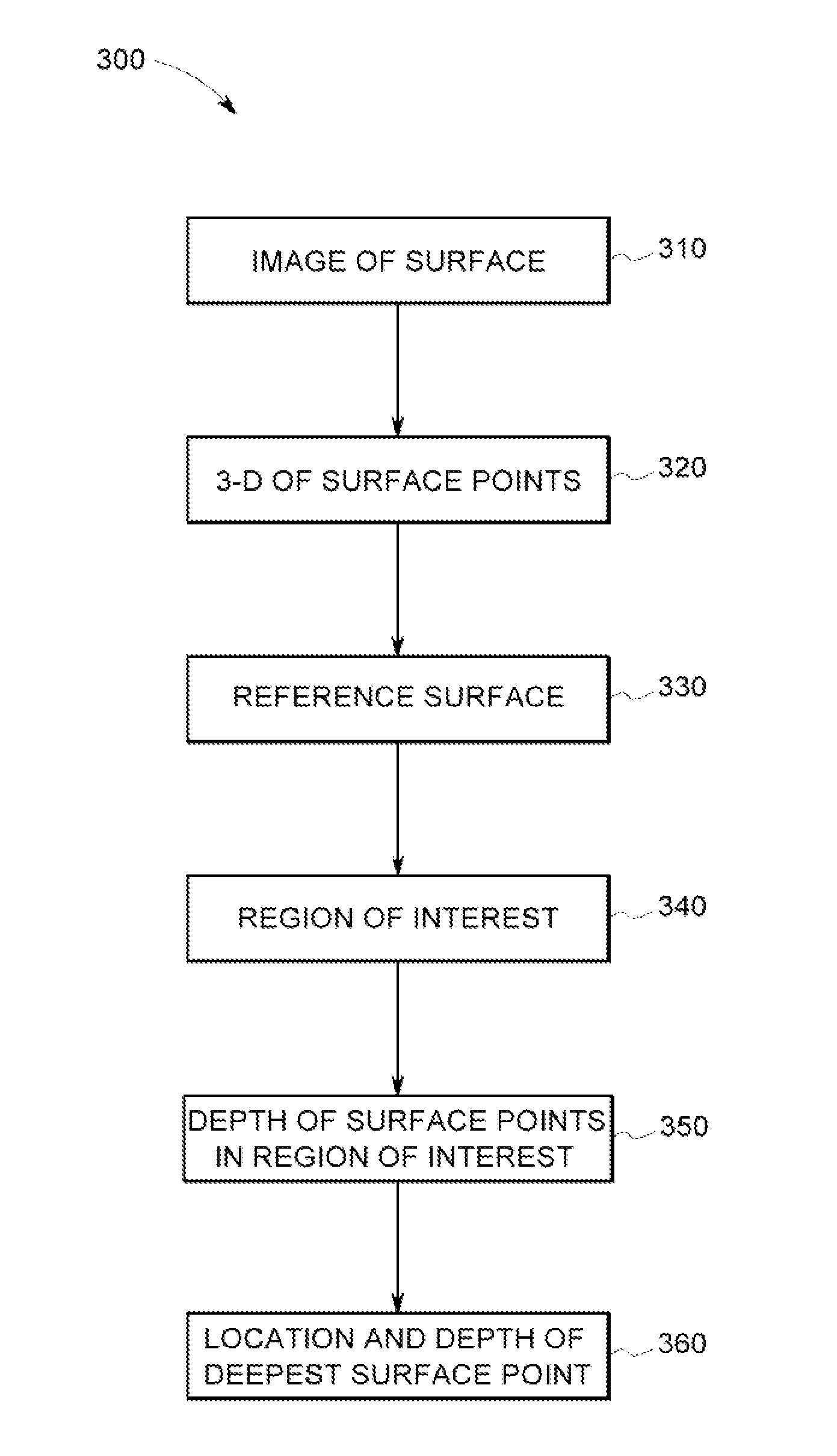
Method and device for automatically identifying a point of interest on the surface of an anomaly
- Summary
- Abstract
- Description
- Claims
- Application Information
AI Technical Summary
Benefits of technology
Problems solved by technology
Method used
Image

Examples
Embodiment Construction
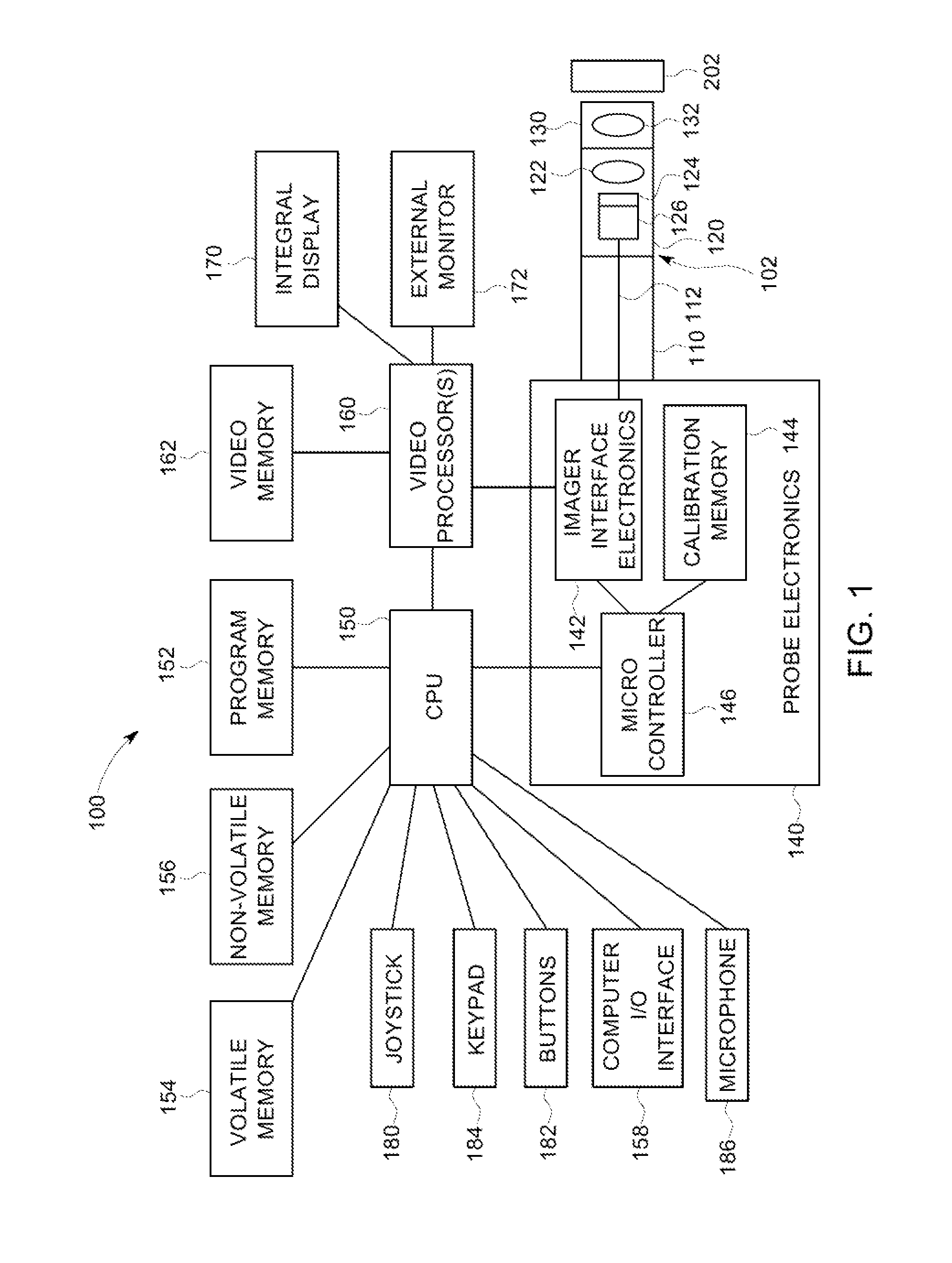
[0024]FIG. 1 is a block diagram of an exemplary video inspection device 100. It will be understood that the video inspection device 100 shown in FIG. 1 is exemplary and that the scope of the invention is not limited to any particular video inspection device 100 or any particular configuration of components within a video inspection device 100.
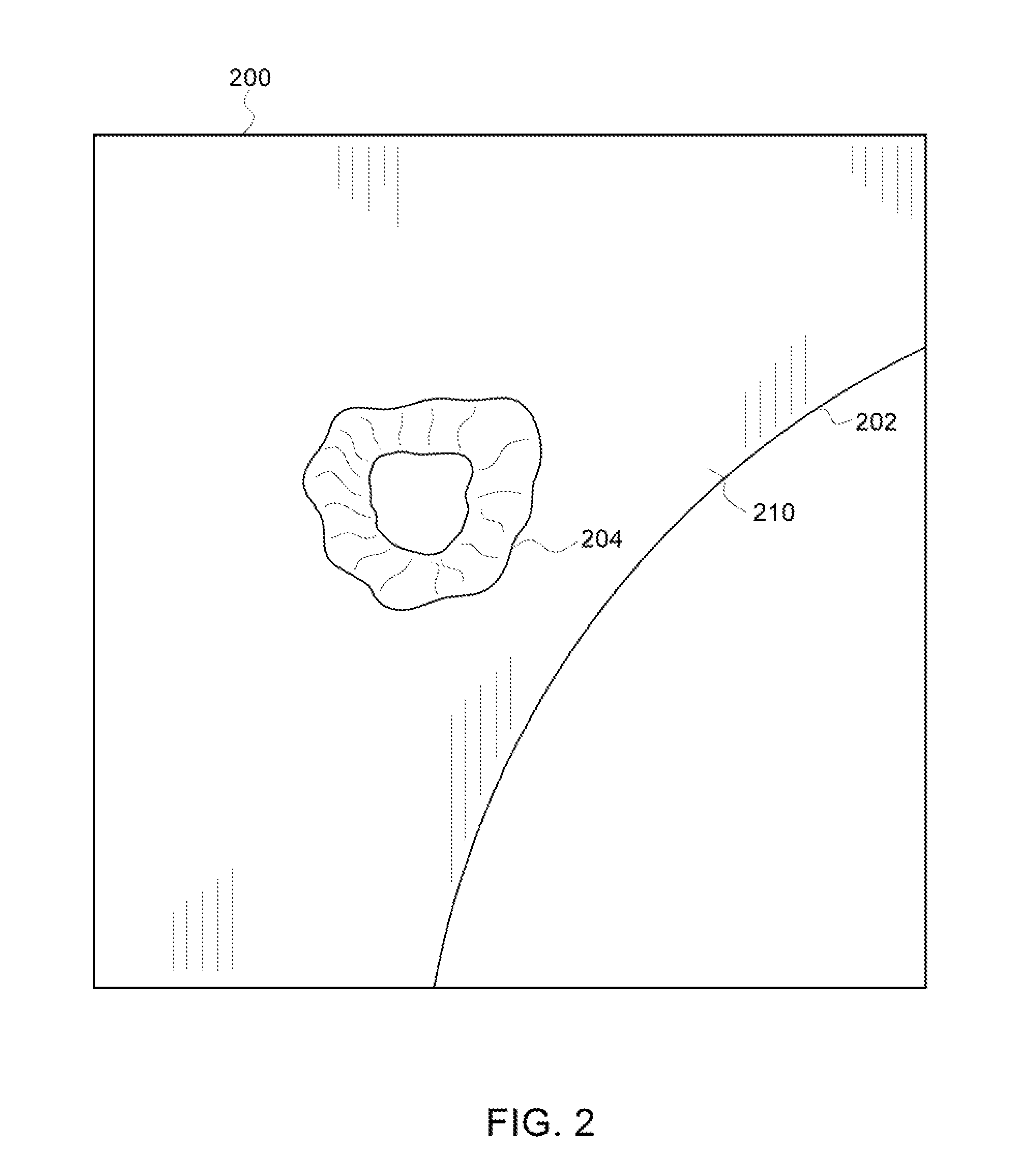
[0025]Video inspection device 100 can include an elongated probe 102 comprising an insertion tube 110 and a head assembly 120 disposed at the distal end of the insertion tube 110. Insertion tube 110 can be a flexible, tubular section through which all interconnects between the head assembly 120 and probe electronics 140 are passed. Head assembly 120 can include probe optics 122 for guiding and focusing light from the viewed object 202 onto an imager 124. The probe optics 122 can comprise, e.g., a lens singlet or a lens having multiple components. The imager 124 can be a solid state CCD or CMOS image sensor for obtaining an image of the viewed o...
PUM
 Abstract
Description
Claims
Application Information