
Image sensor and method for fabricating the same

Active Publication Date: 2015-06-18
SK HYNIX INC
View PDF1 Cites 32 Cited by
  • Summary
  • Abstract
  • Description
  • Claims
  • Application Information

AI Technical Summary

Benefits of technology

The invention aims to improve image sensor performance by preventing the generation of photo-charges that cause noise in the floating diffusion region. This is achieved by adding a barrier layer to the region, which results in a reduction in signal to noise ratio and improved image sensor quality.

Problems solved by technology

However, conventional image sensors generate unwanted photo-charges in regions other than the photoelectric conversion region.
The unwanted photo-charges cause noise in the pixel signal resulting in an increased signal to noise ratio and deteriorated image sensor characteristics.

Method used


Image

  • Image sensor and method for fabricating the same
  • Image sensor and method for fabricating the same
  • Image sensor and method for fabricating the same

Examples


Embodiment Construction

[0024]Exemplary embodiments of the present invention will be described below in more detail with reference to the accompanying drawings. The present invention may, however, be embodied in different forms and should not be construed as limited to the embodiments set forth herein. Rather, these embodiments are provided so that this disclosure will be thorough and complete, and will fully convey the scope of the present invention to those skilled in the art. Throughout the disclosure, reference numerals correspond directly to the like parts in the various figures and embodiments of the present invention.

[0025]The drawings are not necessarily to scale and, in some instances, proportions may have been exaggerated in order to clearly illustrate features of the embodiments. In this specification, specific terms have been used. The terms are used to describe the present invention and are not used to qualify the sense or limit the scope of the present invention.

[0026]It is also noted that in...


PUM


Abstract

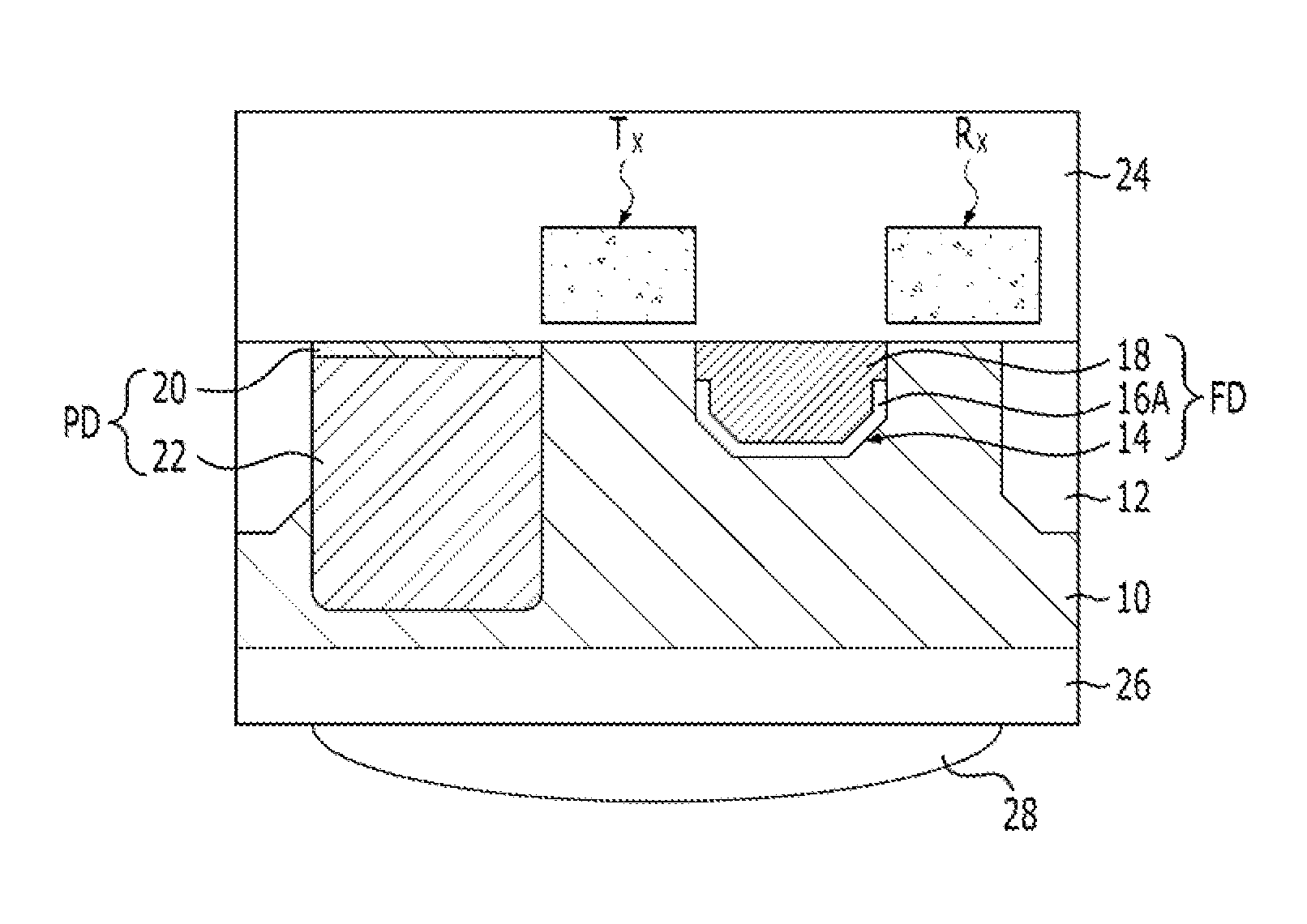
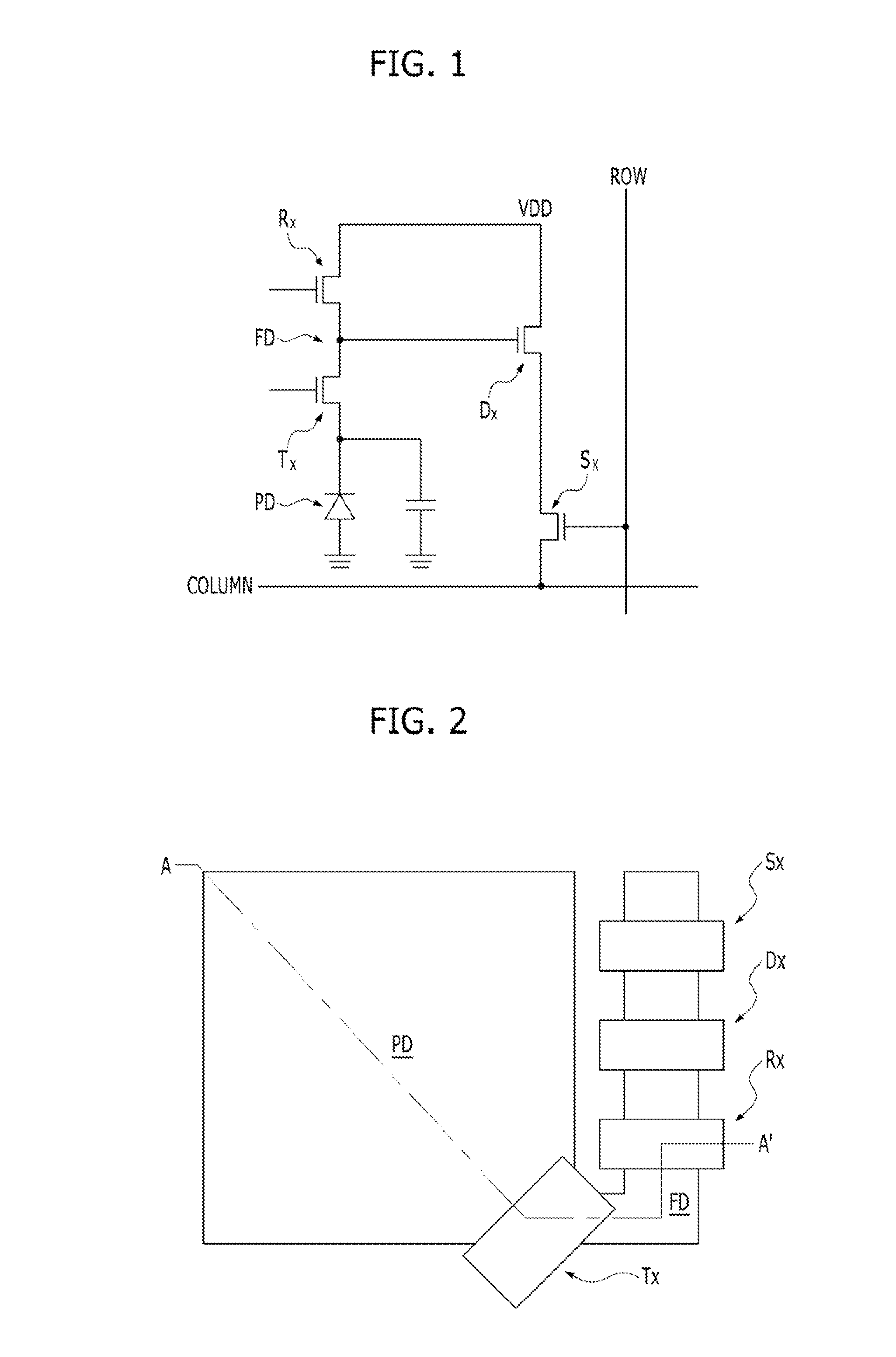
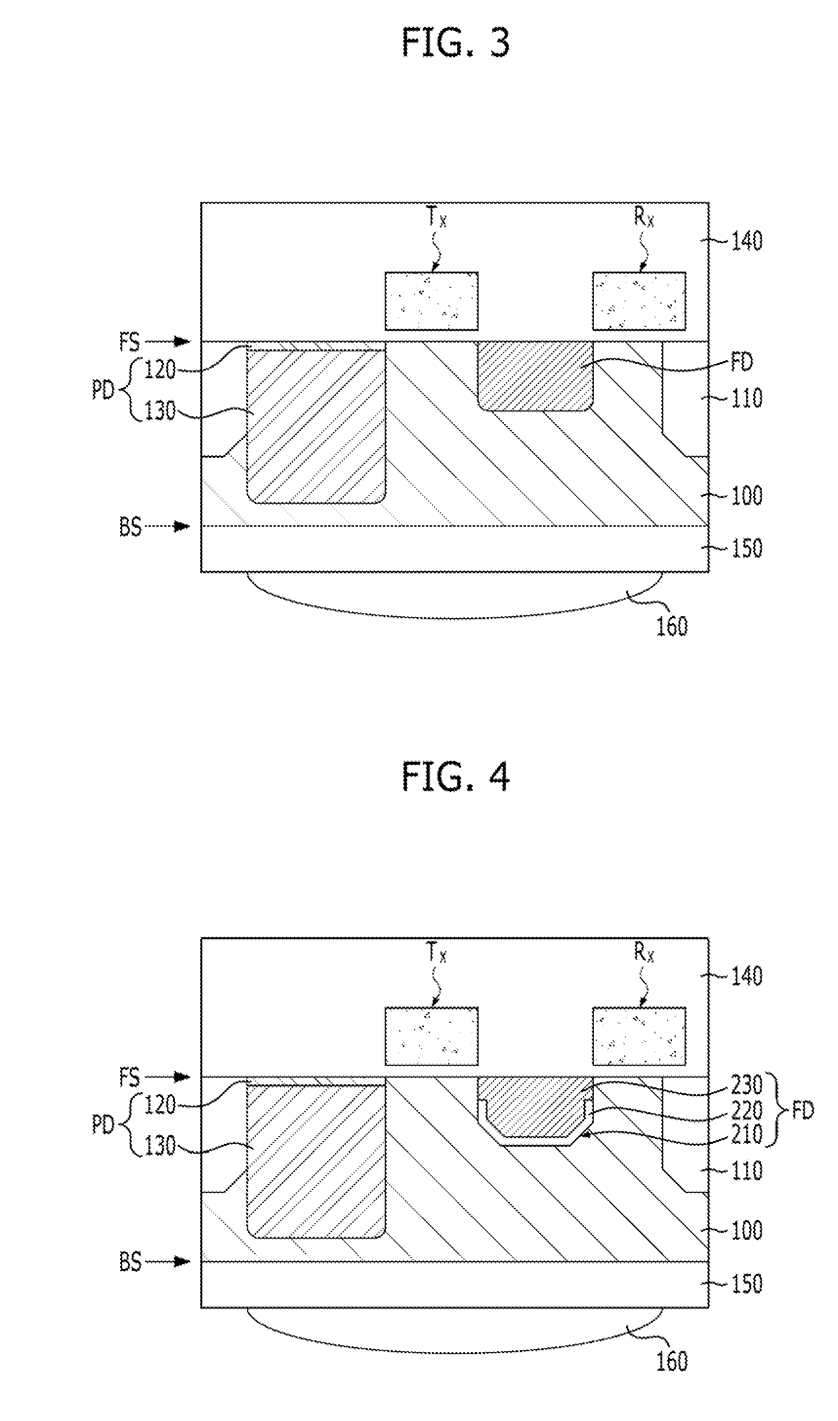
An age sensor including a transfer gate formed on a substrate, a photoelectric conversion region formed on a side of the transfer gate, a floating diffusion region with a trench formed on another side of the transfer gate, a barrier layer which covers a bottom of the trench and a conducting layer, which is gap-filled in the trench.

Description

CROSS-REFERENCE TO RELATED APPLICATIONS[0001]The present application claims priority of Korean Patent Application No. 10-2013-0158162, filed on Dec. 18, 2013, which is incorporated herein by reference in its entirety.BACKGROUND[0002]1. Field[0003]Exemplary embodiments of the present invention relate to a semiconductor design technology, and more particularly, to an image sensor and a method for fabricating the same.[0004]2. Description of the Related Art[0005]An image sensor is a semiconductor element which changes a photonic image into an electrical signal. Image sensors generally include a plurality of pixels that are arranged in the shape of a two-dimensional matrix. Each of the pixels contains a photoelectric conversion region that generates a photo-charge in response to incident light and uses the photo-charge outputs to output a pixel signal.[0006]However, conventional image sensors generate unwanted photo-charges in regions other than the photoelectric conversion region. The ...

Claims


Application Information

Patent Timeline
IPC IPC(8): H01L27/146
CPCH01L27/14645H01L27/14623H01L27/14627H01L27/14621H01L27/1464H01L27/14643H01L27/1461H01L27/14612H01L29/76816H01L29/76825H01L27/146
Inventor KIM, DO-HWANYANG, YUN-HEEKIM, DAE-WOOKIM, JONG-CHAELIM, SU-HWAN
Owner SK HYNIX INC
Learn More