Repeater otdr using repeater based raman pumps

a repeater and raman technology, applied in transmission monitoring, transmission monitoring/testing/fault-measurement systems, electrical equipment, etc., can solve the problems of enormous technical challenges of optical signals over such long distances using wdm or dwdm, and the less relevant of geographical location

Active Publication Date: 2015-06-18
NEPTUNE SUBSEA IP LTD
View PDF13 Cites 22 Cited by
  • Summary
  • Abstract
  • Description
  • Claims
  • Application Information

AI Technical Summary

Benefits of technology

[0005]At least one embodiment described herein relates to an optically pumped amplifier assembly that comprises a fiber fault detection module. The assembly includes an optically pumped amplifier that amplifies optical signals in a signal path. Furthermore, a sensor ...

Problems solved by technology

Transmission of optical signals over such long distances using WDM or DWDM presents enormous technical challenges, especially at high bit rates in the gigabits per second per chan...

Method used


Image

  • Repeater otdr using repeater based raman pumps
  • Repeater otdr using repeater based raman pumps
  • Repeater otdr using repeater based raman pumps

Examples


Embodiment Construction

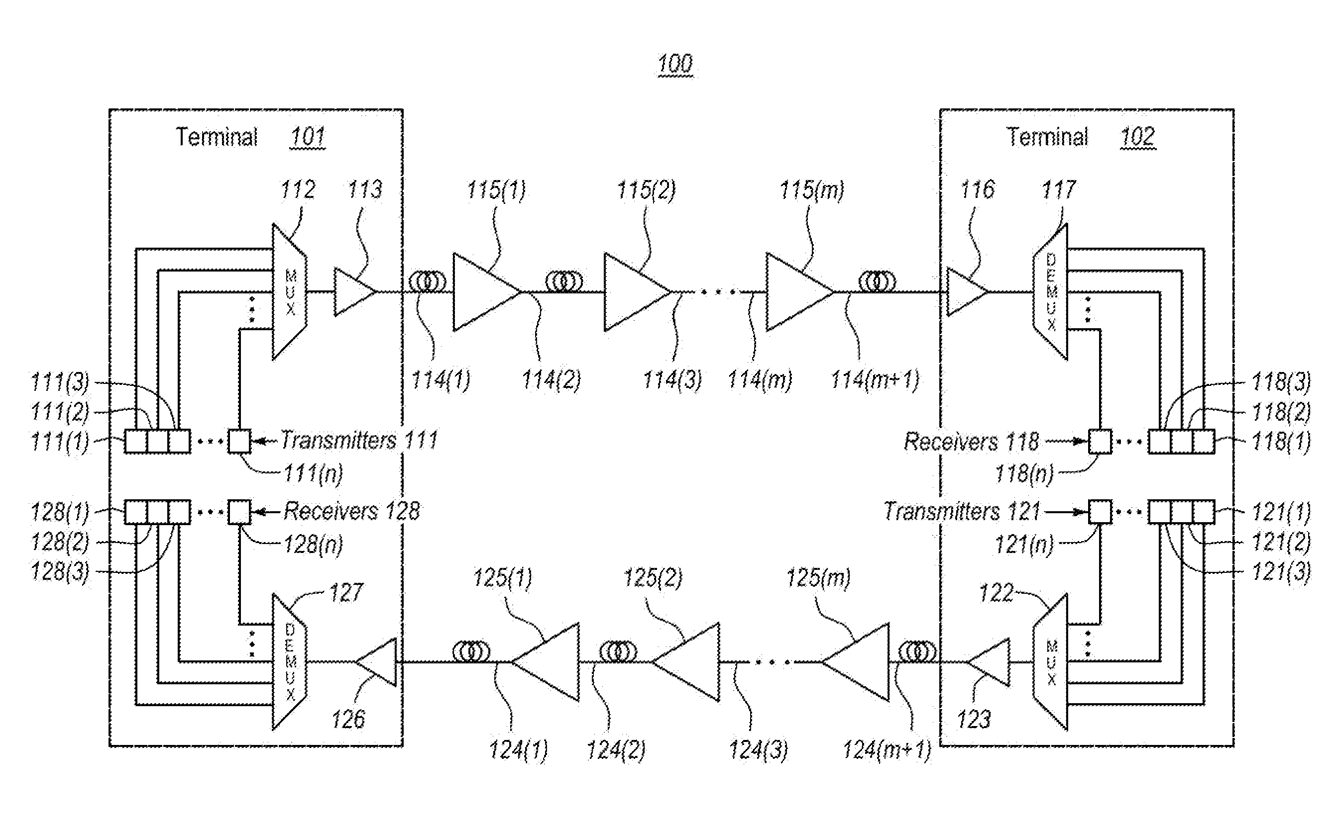
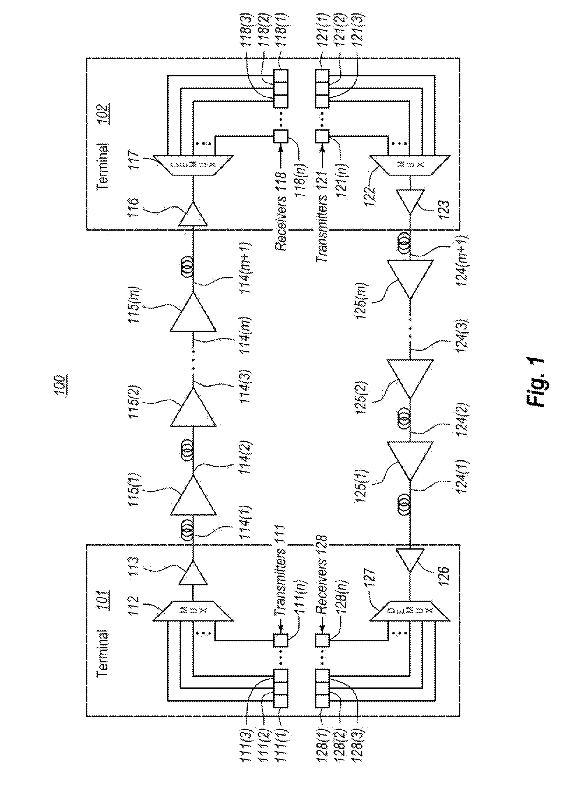
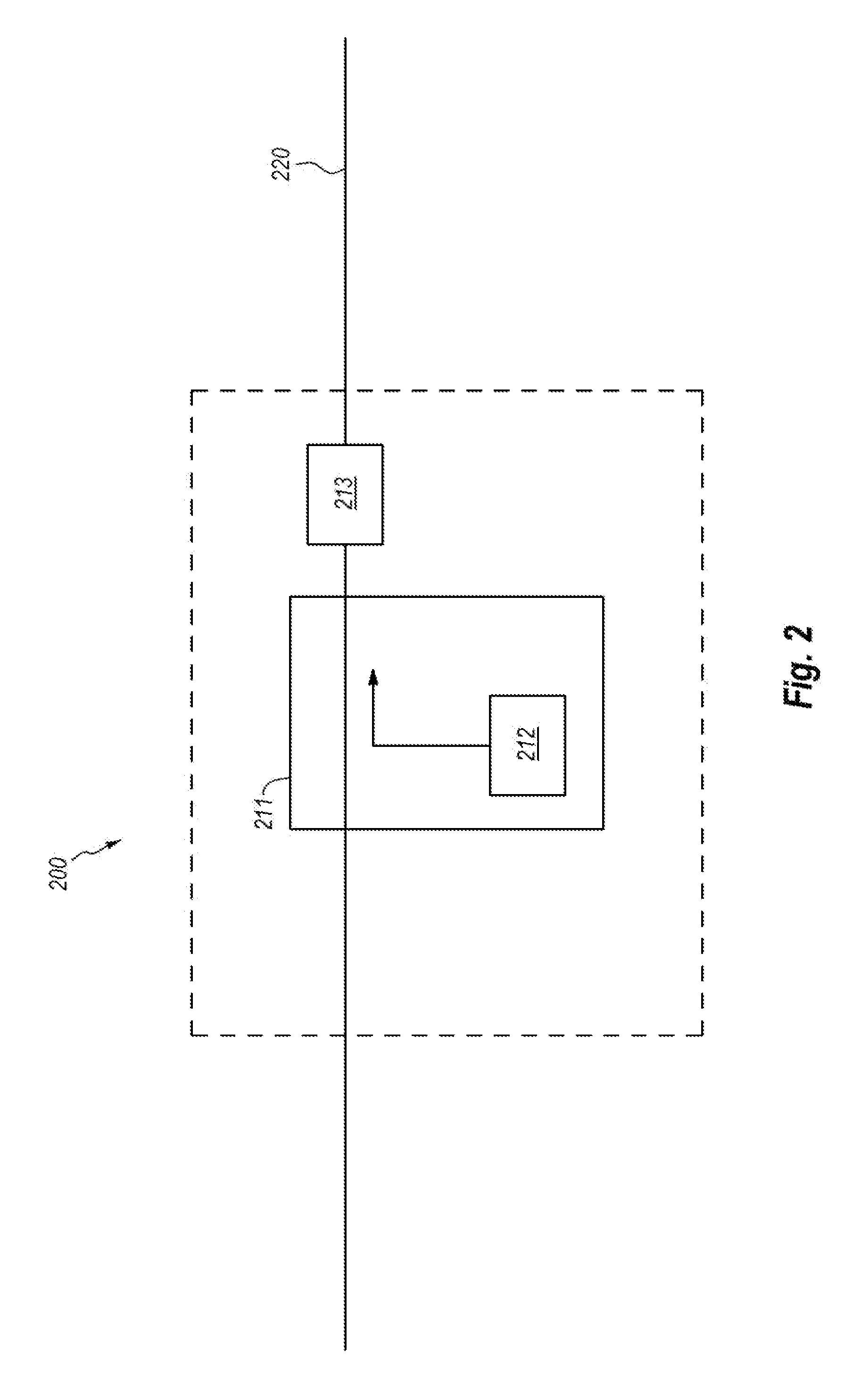
[0017]In accordance with embodiments described herein, a submarine optical amplifier assembly comprising an optical fiber fault detection module is described. The assembly can include an optically pumped amplifier that amplifies optical signals in a signal path. A sensor can be disposed within the fiber fault detection module. The sensor can analyze an optical signal at the amplifier assembly. The analyzed optical signal can provide information relating to the presence and location of a fault within the optical fiber.

[0018]A method for remote cable fault location can be beneficial in a Long haul optical transmission system in order to facilitate a repair. Conventionally, schemes have been based on remote measurement of light levels using telemetry, or cable end voltages in order to locate a fault. Such methods are somewhat limited to a resolution on the order of a cable span (40-80 km). By implanting an OTDR (optical time domain reflectometry) scheme within a repeater, the resolutio...


PUM


Abstract

A submarine optical repeater includes a submarine amplifier module, which further includes a pumping laser module and an optical detector module. The pumping laser module generates optical amplifications within an optical cable, and, in the case of a fault in the optical cable, the optical detector module detects at least one characteristic of an optical signal caused by the fault in the optical cable. This configuration then identifies a particular signal characteristic that indicates a fault within the optical cable.

Description

BACKGROUND[0001]Fiber-optic communication networks serve a key demand of the information age by providing high-speed data between network nodes. Fiber-optic communication networks include an aggregation of interconnected fiber-optic links. Simply stated, a fiber-optic link involves an optical signal source that emits information in the form of light into an optical fiber. Due to principles of internal reflection, the optical signal propagates through the optical fiber until it is eventually received into an optical signal receiver. If the fiber-optic link is bi-directional, information may be optically communicated in reverse typically using a separate optical fiber.[0002]Fiber-optic links are used in a wide variety of applications, each requiring different lengths of fiber-optic links. For instance, relatively short fiber-optic links may be used to communicate information between a computer and its proximate peripherals, or between a local video source (such as a DVD or DVR) and a ...

Claims


Application Information

Patent Timeline
IPC IPC(8): H04B10/071H04B10/80H04B10/073
CPCH04B10/071H04B10/80H04B10/0731H04B10/0777
Inventor WEBB, STEPHEN MICHAELPELOUCH, WAYNE S.CHANG, DO-ILELLISON, JOHN G.
Owner NEPTUNE SUBSEA IP LTD
Why Eureka
Try Eureka