Helicopter with h-pattern structure

a helicopter and h-pattern technology, applied in the direction of rotors, emergency equipment, vehicles, etc., can solve the problems of severe restrictions derived from the main rotor of the helicopter, the structure of the tail rotor is also complex, and the helicopter is also set back by severe restrictions, so as to achieve simple mechanical structure, enhance safety and operation, and maintain flight balance

Inactive Publication Date: 2015-06-25
LEE HUNG FU
View PDF18 Cites 31 Cited by
  • Summary
  • Abstract
  • Description
  • Claims
  • Application Information

AI Technical Summary

Benefits of technology

[0010]The invention is directed to a helicopter with an H-pattern structure, more particularly to a helicopter that has a simple mechanical structure and is capable of maintaining flight balance as well as controlling a flight posture and rotation direction, thereby enhancing the safety and operations as well as increasing the flying speed of the helicopter.
[0011]To achieve the above objects, a helicopter with an H-pattern structure is provided by the present invention. In the present invention, with an H-pattern transmission mechanism operating in collaboration with two pairs of rotor sets, which are disposed at two sides of a front region and a rear region of an airframe and being rotated in opposite directions, torques generated by the two pairs of rotor sets being rotated in the opposite directions are counteracted. Thus, a flight posture and rotation direction during a flight of the helicopter is kept balanced, and at the same time, the helicopter is provided with a simple structure and ensured flight safety.
[0013]The H-pattern transmission mechanism includes an engine, a set of transmission mechanism, two deceleration gear boxes and a plurality of transmission shafts. The transmission mechanism includes a main transmitting wheel and a transmitted wheel. The main transmitting wheel is connected to the engine, and the transmitted wheel is connected to the two deceleration gear boxes by one transmission shaft. The two deceleration gear boxes are connected to the gear boxes of each of the rotor sets, thereby evenly transmitting the power outputted from the engine to each of the rotor sets.
[0015]Further, the airframe may be designed as a boat shape, which allows the helicopter to safely float on the sea in the event of a power loss of the helicopter.

Problems solved by technology

However, helicopters are also set back by severe restrictions derived from principles of flight of helicopters.
Although the helicopter is a convenient air transportation means, in order to at the same time provide effects of tilting forward and backward as well as left and right and thus allowing the helicopter to freely fly in the sky, the main rotor of the helicopter has an extremely complex design.
Moreover, the structure of the tail rotor is also complex for it needs to provide a high thrust at one moment and a low thrust at another.
The main rotor and rear rotor of a conventional helicopter are designed with sophisticated structures in a way that piloting such helicopter is made quite challenging.
Further, such helicopter is prone to unbalanced flights, and the flight speed is also limited by the main rotor.
Further, due to the provision of the main rotor, neither injection seats nor parachutes can be installed on the helicopter, meaning that the helicopter is fated for an inevitable crash in the event of a machinery malfunction and hence pilot casualties.
Although the helicopter is designed with an auto rotation function, such flying technique requires tens to hundreds of hours of professional training and offers no 100% guarantee of safety.

Method used


Image

  • Helicopter with h-pattern structure
  • Helicopter with h-pattern structure
  • Helicopter with h-pattern structure

Examples


Embodiment Construction

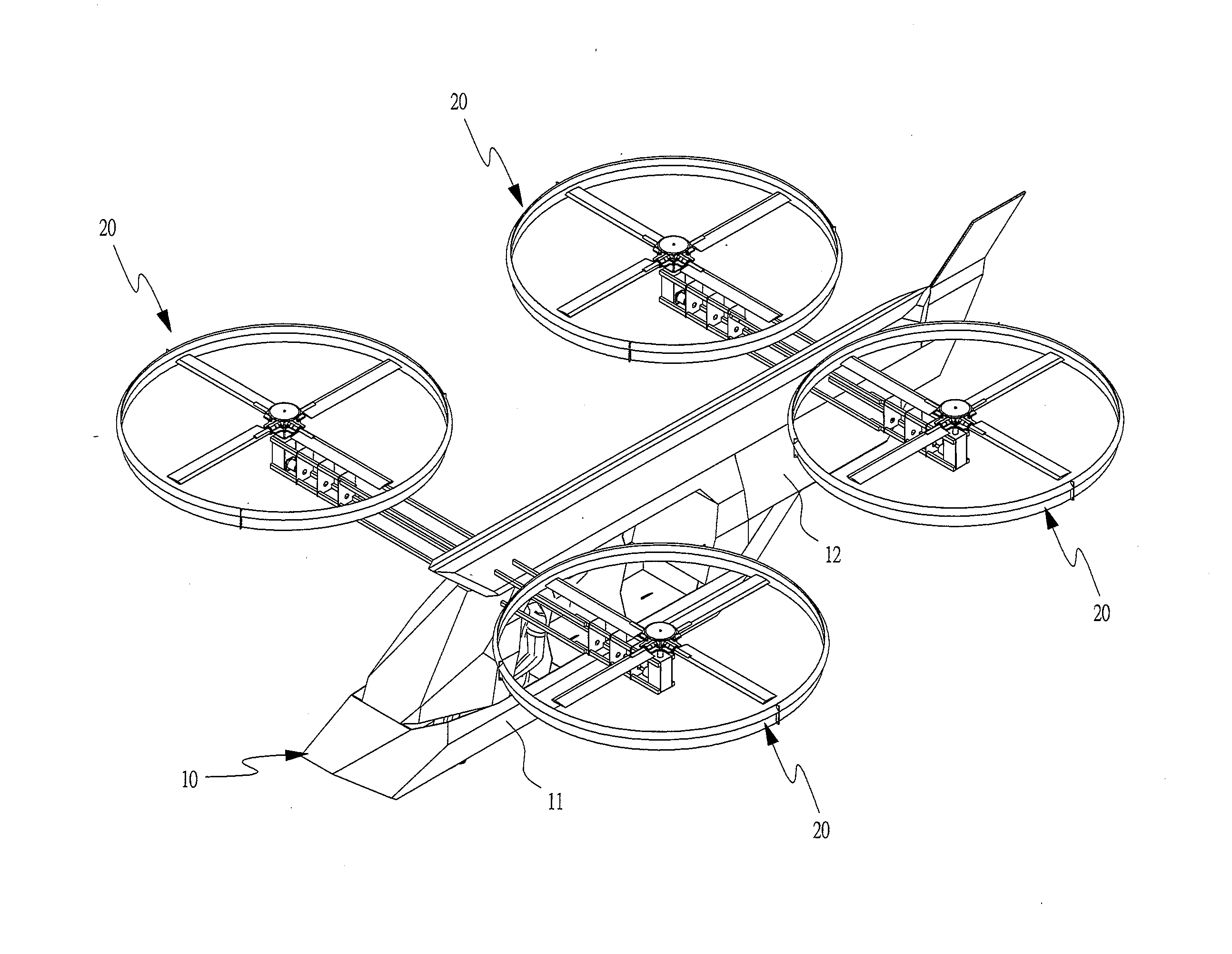
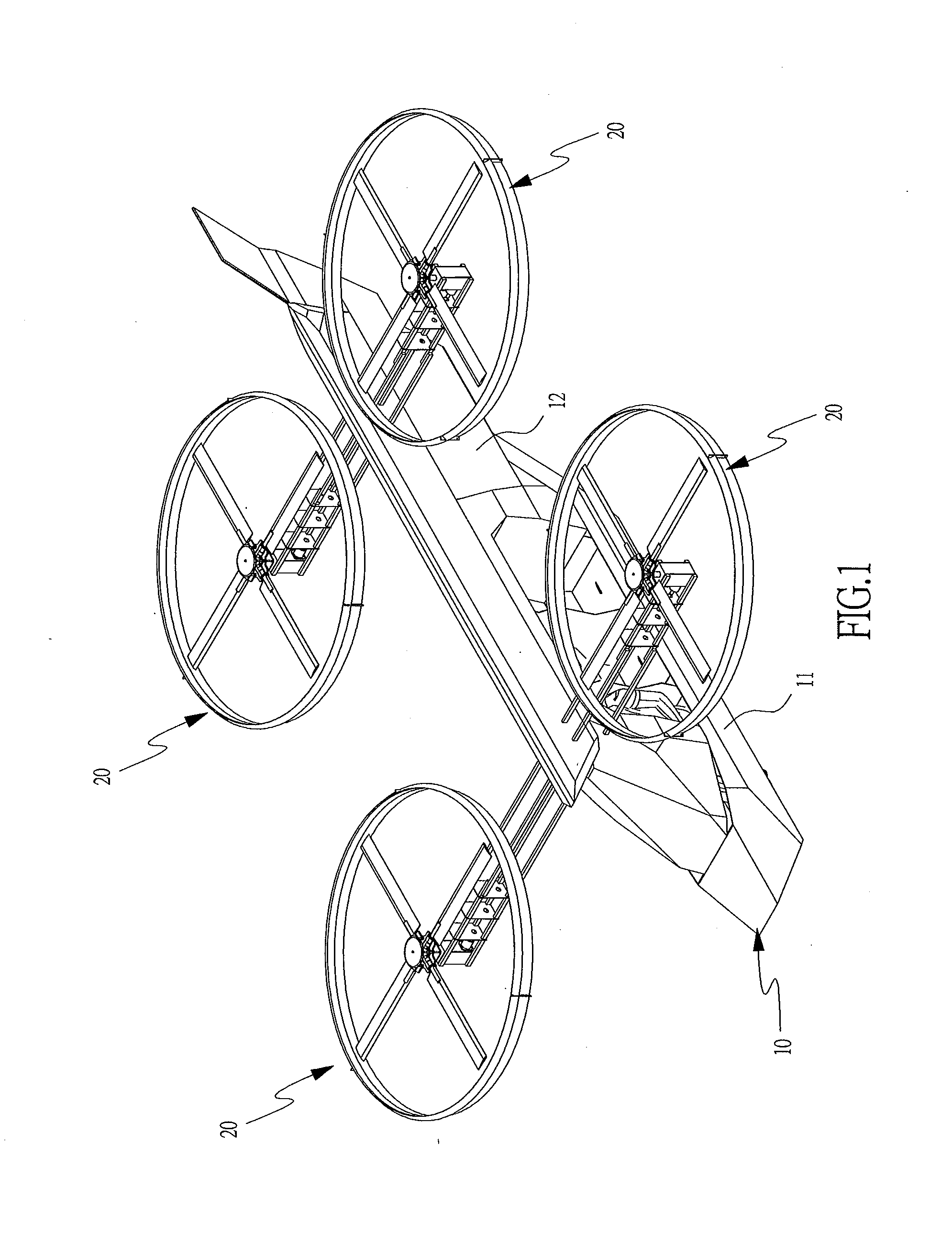
[0030]Referring to FIGS. 1 and 2, a helicopter with an H-pattern structure of the present invention includes an airframe 10, four rotor sets 20, an H-pattern transmission mechanism (to be described shortly), and a control device (to be described shortly).

[0031]The airframe 10 includes a front region 11 and a rear region 12. The front region 11 is internally provided with a cockpit for carrying a passenger and providing operations of the helicopter. The rear region 12 is an extension from the rear of the front region 11.

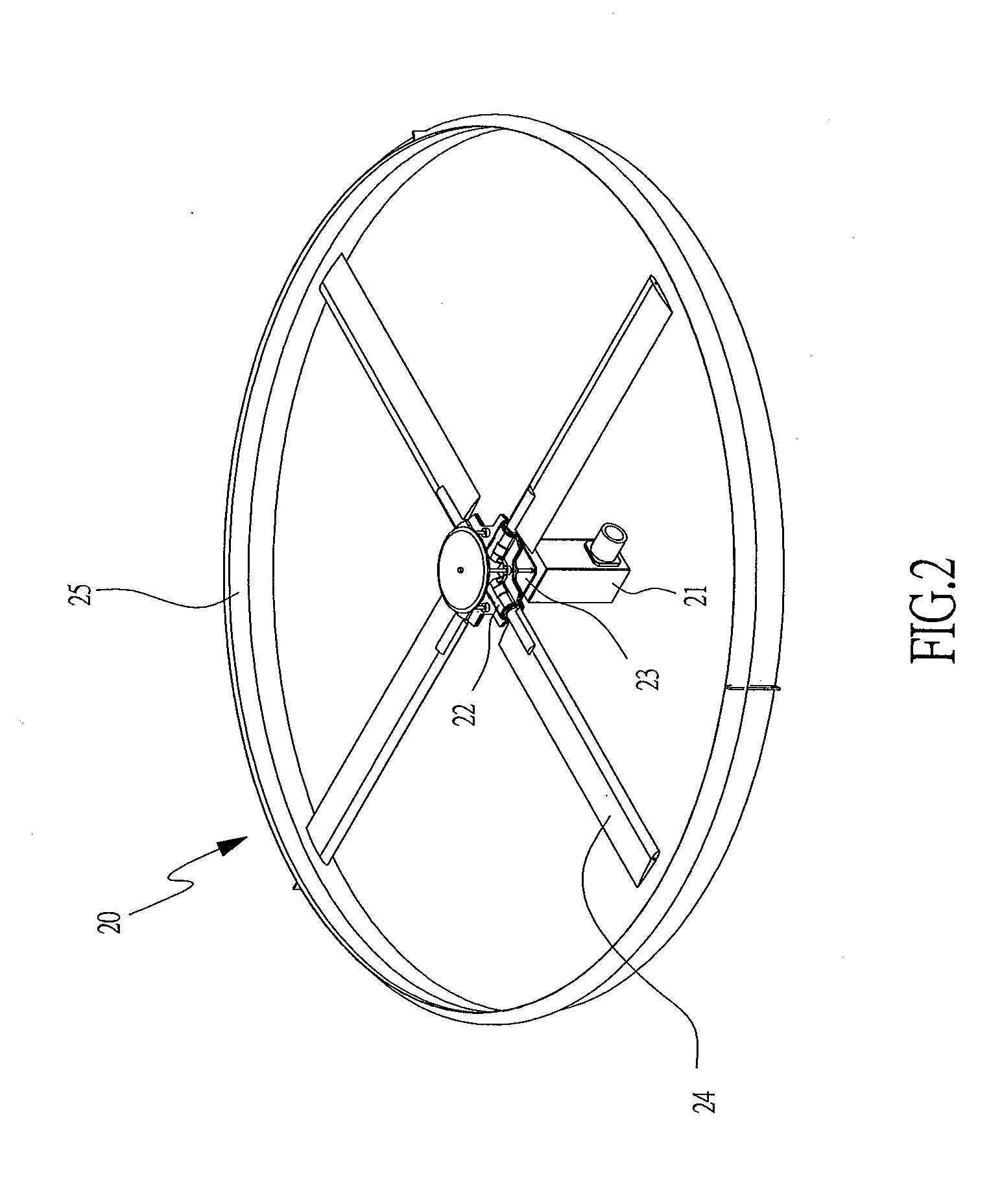
[0032]The four rotor sets 20 are paired, i.e., two front rotor sets are paired and two rear rotor sets are paired, to form a pair of front rotor sets and a pair of rear rotor sets. Each of the rotor sets 20 includes a gear box 21, a power angle control module 22, a linear servo motor 23, at least one propeller 24, and a windshield 25. The gear box 21 is connected to the H-pattern transmission mechanism. The power angle control module 22 drives the linear servo motor 2...


PUM


Abstract

A helicopter with an H-pattern structure is provided. With an H-pattern transmission mechanism operating in collaboration with two pairs of rotor sets, which are disposed at two sides of a front region and a rear region of an airframe and being rotated in opposite directions, torques generated by the two pairs of rotor sets being rotated in opposite directions are counteracted. Thus, a flight posture and rotation direction during a flight of the helicopter is kept balanced, and at the same time, the helicopter is provided with a simple structure and ensured flight safety.

Description

BACKGROUND OF THE INVENTION[0001]A) Field of the Invention[0002]The invention relates in general to a helicopter with an H-pattern structure, and more particularly to a helicopter that has a simple mechanical structure and is capable of maintaining flight balance as well as controlling a flight posture and rotation direction for ensuring flight safety.[0003]b) Description of the Prior Art[0004]Helicopters have long been one of the most convenient air transportation means and essential air forces. The prominence of helicopters is contributed by the vertical ascending and vertical descending capabilities without involving approach tracks. However, helicopters are also set back by severe restrictions derived from principles of flight of helicopters.[0005]In a conventional helicopter, a main rotor and a tail rotor that have orthogonally staggered axial centers are propelled by a same engine power. The main rotor controls the ascending and descending as well as forward, backward, left an...

Claims


Application Information

Patent Timeline
Patent Type & Authority Applications(United States)
IPC IPC(8): B64C27/08B64D17/80
CPCB64D17/80B64C27/08B64C27/14B64C27/20B64C27/473B64D25/00
Inventor LEE, HUNG-FU
Owner LEE HUNG FU
Why Eureka
Try Eureka