Method for determining hydraulic fracture orientation and dimension
- Summary
- Abstract
- Description
- Claims
- Application Information
AI Technical Summary
Benefits of technology
Problems solved by technology
Method used
Image
Examples
example 1
[0035]In this Example, pressure gauges were installed downhole and monitored during multi-stage hydraulic fracturing of horizontal wells in a shale formation located in Eagle Ford Formation located near San Antonio, Tex.
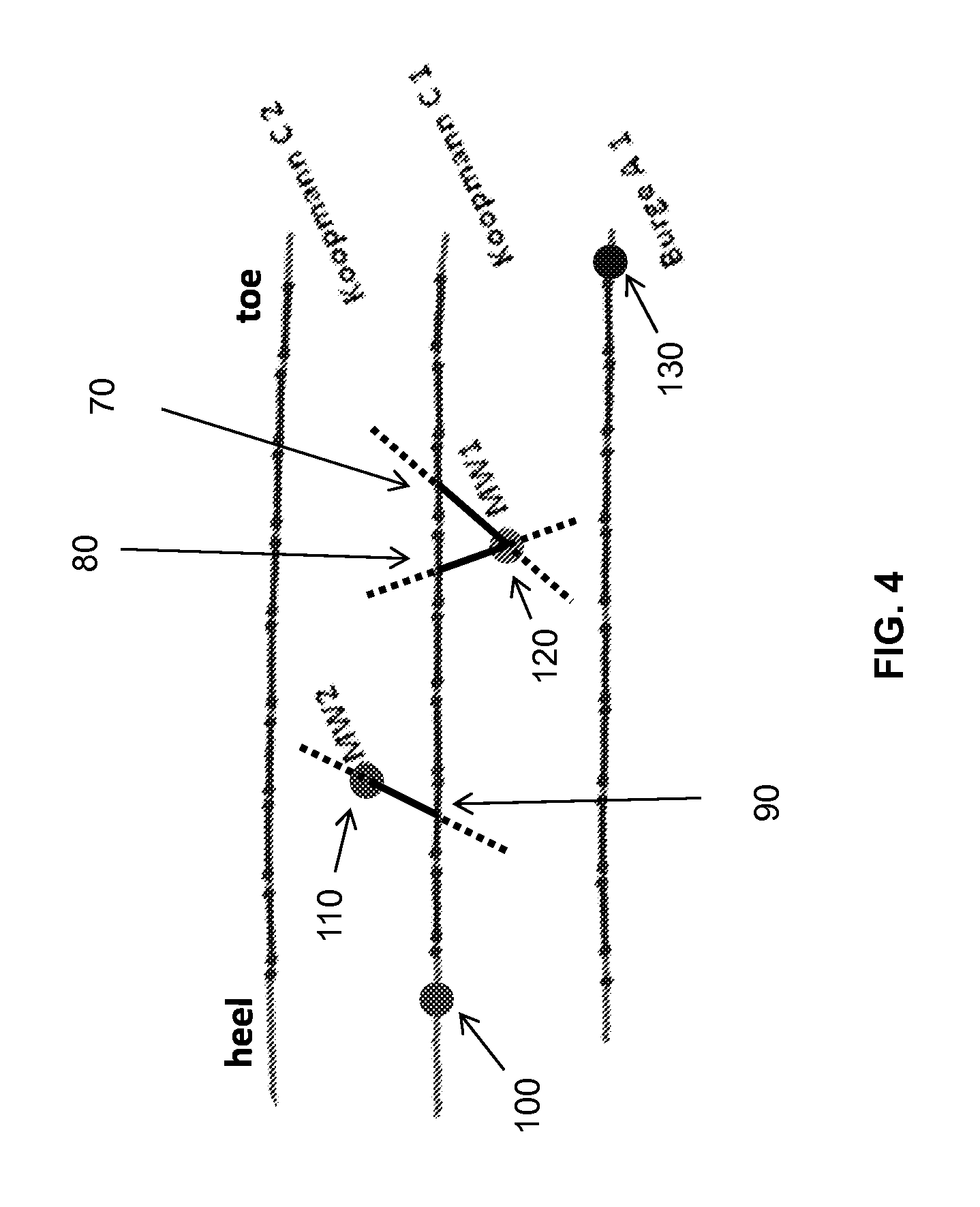
[0036]FIG. 4 shows a configuration of active (Koopmann C1) and offset (Burge A1, Koopman C2) wells and monitoring wells (MW1, MW2) used in this Example. Pressure gauges (100, 110, 120, 130) were installed in two of the wells (Koopmann C1 and Burge A1) as well as both monitoring wells (MW1 and MW2). Initial stages of the multi-stage hydraulic fracturing process start at toe end of the horizontal wells while each subsequent fracturing stage starts closer and closer to heel end of the horizontal well. As illustrated, hydraulic communication between the monitoring wells and Koopmann C1 is present during various fracturing stages 70, 80, and 90.
[0037]FIG. 5 plots pressure response recorded by the pressure gauges as a function of time. Koopmann C1 and Burge A1 were subject...
PUM
 Abstract
Description
Claims
Application Information
 - Generate Ideas
- Intellectual Property
- Life Sciences
- Materials
- Tech Scout
- Unparalleled Data Quality
- Higher Quality Content
- 60% Fewer Hallucinations
Browse by: Latest US Patents, China's latest patents, Technical Efficacy Thesaurus, Application Domain, Technology Topic, Popular Technical Reports.
© 2025 PatSnap. All rights reserved.Legal|Privacy policy|Modern Slavery Act Transparency Statement|Sitemap|About US| Contact US: help@patsnap.com


