Apparauts for fluid pumping

a technology of apparatuses and fluids, applied in the direction of pump control, positive displacement liquid engines, pumping, etc., can solve the problems of increasing the lifting requirement of reducing the lifting requirement, and not having enough reservoir pressure to push fluid to the surface, etc., to achieve the effect of small footprint, minimal maintenance requirements, and simple operation

Inactive Publication Date: 2015-06-25
SOTZ LEONARD C +1
View PDF13 Cites 2 Cited by
  • Summary
  • Abstract
  • Description
  • Claims
  • Application Information

AI Technical Summary

Benefits of technology

[0015]Said at least one hydraulic cylinder assembly can be beneficially mounted to said elongate tower assembly using a self-centering pivot mounting assembly. Said self-centering pivot mounting assembly ensures that said at least one hydraulic cylinder assembly finds the center of gravity, thereby preventing unwanted side loading on said at least one cylinder assembly.
[0017]The hydraulic pumping apparatus of the present invention is inexpensive, durable and simple to operate. Further, the hydraulic pumping apparatus of the present invention has a small footprint and can be directly mounted to wells having shallow to medium depths or, alternatively, skid supported for wells extending to deeper depths. The hydraulic pumping apparatus of the present invention further provides for precise rod speed control with minimal maintenance requirements. Stroke speed can be easily and quickly adjusted without the need for expensive, troublesome or complicated electronic equipment.

Problems solved by technology

However, depending on the depth of the reservoir and density of the fluid(s), the reservoir may not have sufficient reservoir pressure to push the fluid to the surface.
However, as a well continues to produce, reservoir pressure will often decrease as a reservoir depletes.
Further, in many reservoirs, formation water will eventually encroach into the wellbore, causing the lifting requirements to be much greater than for just oil and / or gas.
Either or both of these conditions can cause production from a well to decline, or possibly even cease entirely.
Said surface drive mechanisms can be large, cumbersome and difficult to install in many instances.
Further, such conventional surface drive mechanisms are typically complicated, and expensive to manufacture, operate and maintain.

Method used


Image

  • Apparauts for fluid pumping
  • Apparauts for fluid pumping
  • Apparauts for fluid pumping

Examples


Embodiment Construction

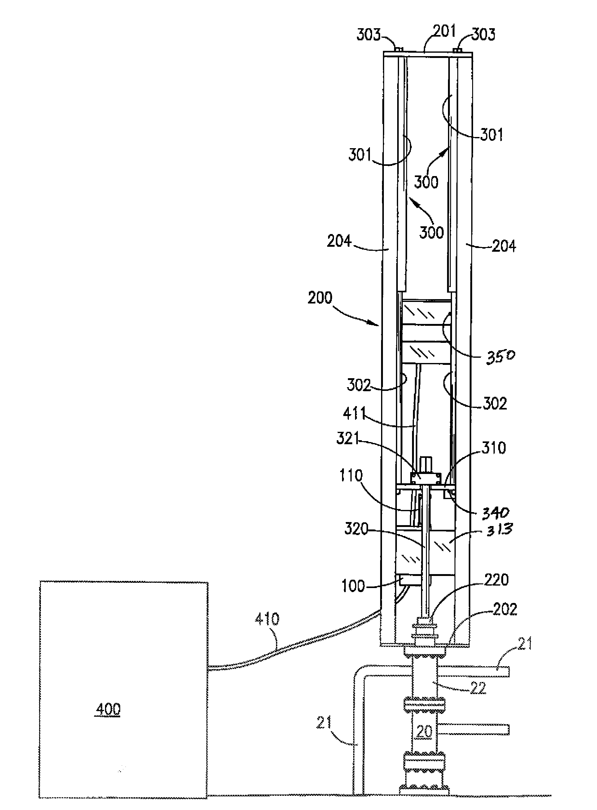
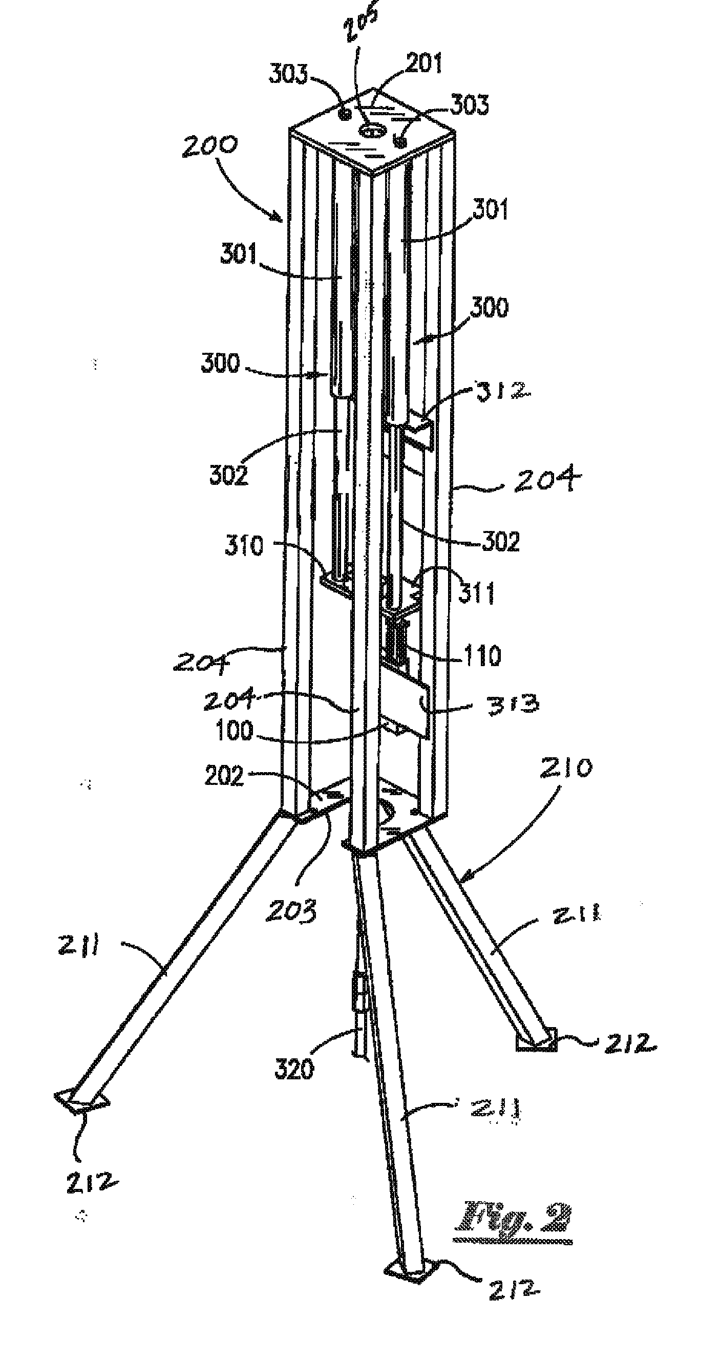
[0039]Referring to the drawings, FIG. 1 depicts a front perspective view of support tower assembly 200 of a hydraulic pumping apparatus 10 of the present invention. Elongate support tower assembly 200 is capable of being mounted to the upper end of a well that extends into the earth's crust. Said tower assembly 200 has substantially planar upper plate member 201 having optional central aperture 205, lower substantially planar plate member 202 having cut-out section 203 and elongate column support members 204 extending between said upper and lower plate members. Support tower assembly 200 provides a rigid support frame for supporting at least one hydraulic cylinder assembly 300. In the preferred embodiment, said elongate tower assembly 200 (and said at least one hydraulic cylinder assembly 300 supported therein) are mounted in substantially axial alignment over a well.

[0040]As depicted in FIG. 1, tandem cylinder assemblies 300 are mounted within support tower assembly 200. Each of sa...


PUM


Abstract

A fluid balanced hydraulic pump has a support tower that can be mounted over a well. At least one cylinder assembly is pivotally mounted within the support tower. A prime mover provides hydraulic fluid to the at least one cylinder assembly through a wedge spool control valve that provides precise speed control with minimal maintenance requirements. Stroke speed can be easily and quickly adjusted without the need for expensive, troublesome or complicated electronic equipment.

Description

CROSS REFERENCES TO RELATED APPLICATION[0001]This application is a continuation of U.S. patent application Ser. No. 13 / 412,196, FILED Mar. 5, 2012, currently pendingSTATEMENTS AS TO THE RIGHTS TO THE INVENTION MADE UNDER FEDERALLY SPONSORED RESEARCH AND DEVELOPMENT[0002]NoneBACKGROUND OF THE INVENTION[0003]1. Field of the Invention[0004]The present invention pertains to a hydraulic pumping unit. More particularly, the present invention pertains to a hydraulic pumping unit that provides precise rod speed control with minimal maintenance requirements.[0005]2. Brief Description of the Prior Art[0006]Liquid-producing subterranean reservoirs all have some level of energy or potential, frequently referred to as “reservoir pressure” that will force fluid (liquid, gas or a mixture) to areas of lower energy or potential. If a well penetrates such a reservoir, and if the pressure inside such a well is decreased below the reservoir pressure, fluids will feed into the well from said formation. ...

Claims


Application Information

Patent Timeline
Patent Type & Authority Applications(United States)
IPC IPC(8): F04B47/04F04B7/00
CPCF04B7/0015F04B47/04F04B7/0007F04B47/08
Inventor SOTZ, LEONARD C.VAN KREVEL, JOHN
Owner SOTZ LEONARD C
Why Eureka
Try Eureka