Magnetic Field Sensor and Method For Sensing Relative Location of the Magnetic Field Sensor and a Target Object Along a Movement Line

a magnetic field sensor and target object technology, applied in the field of magnetic field sensors, can solve the problems of conventional magnetic field sensors, gear tooth sensors, and inability to provide an output signal representativ

Active Publication Date: 2015-06-25
ALLEGRO MICROSYSTEMS INC
View PDF6 Cites 31 Cited by
  • Summary
  • Abstract
  • Description
  • Claims
  • Application Information

AI Technical Summary

Benefits of technology

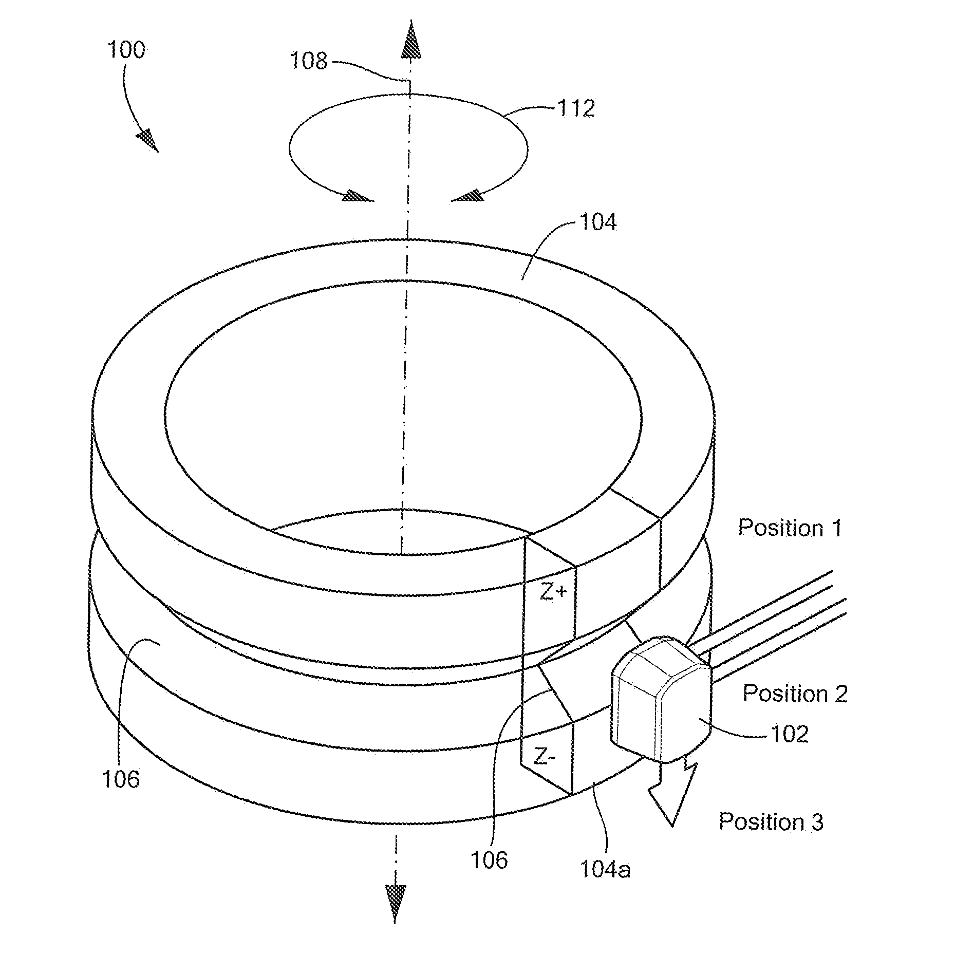
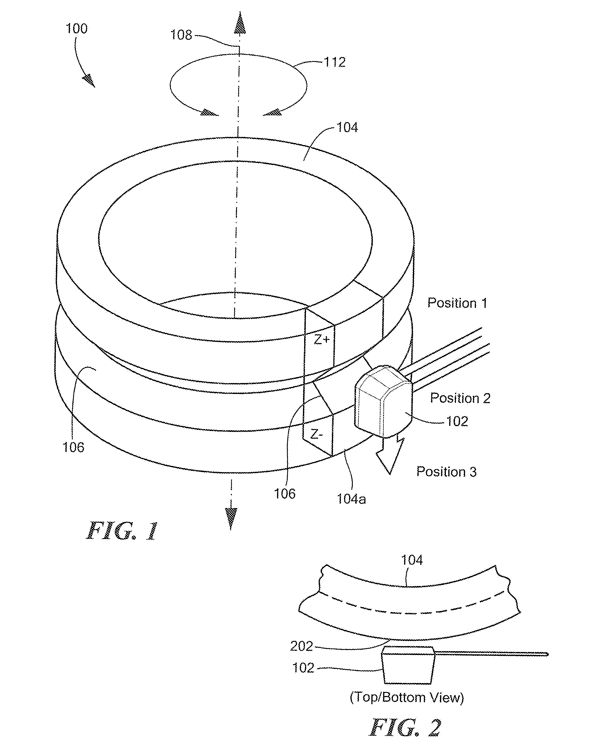
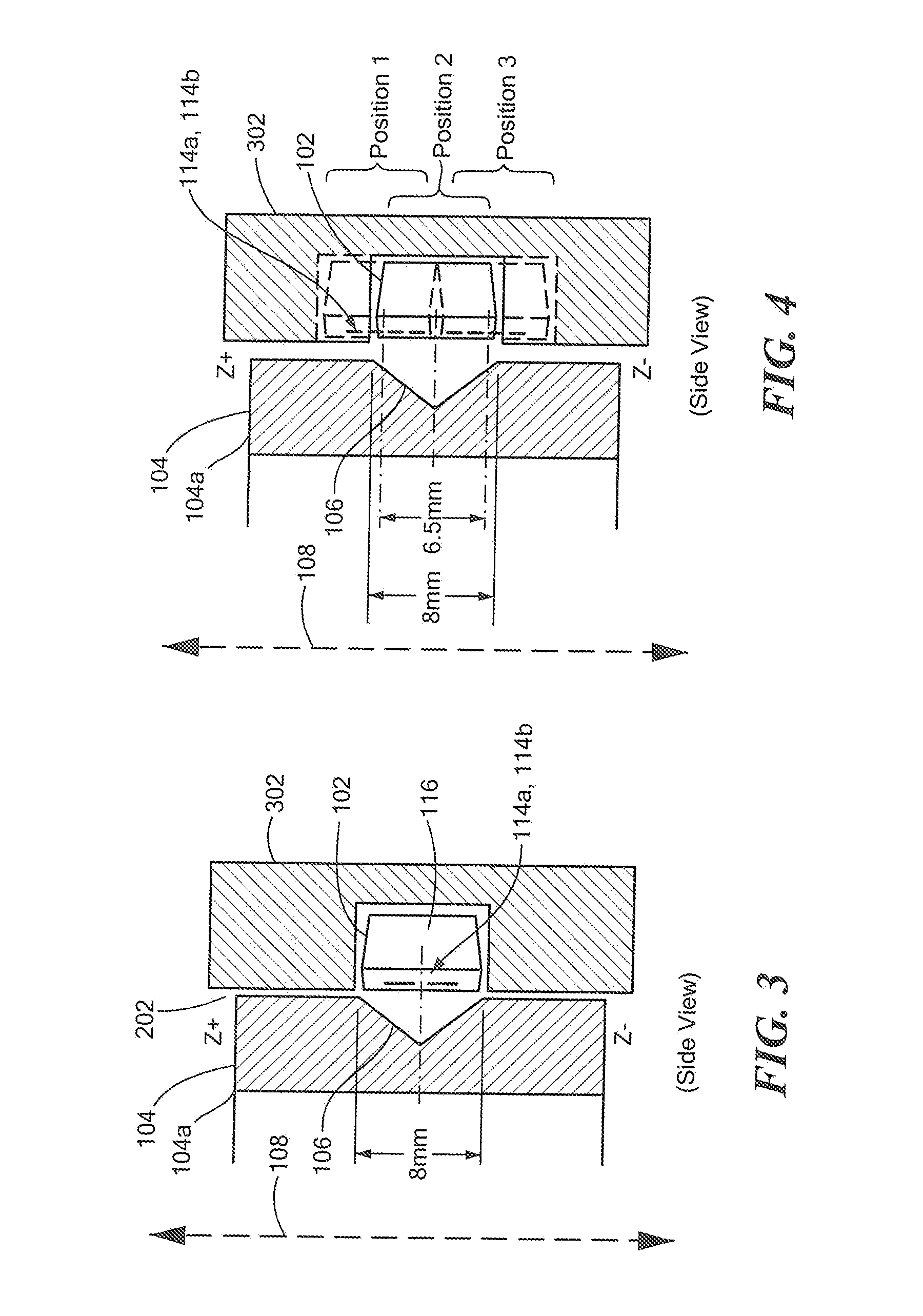
[0013]The present invention provides a magnetic field sensor and method that can generate an output signal representative of a relative location of the magnetic field sensor and a target object in an axial direction along a movement line. The present invention also provides a magnetic field sensor that can generate the above output signal both if the target object is spinning and also if the target object is not spinning about the axis.

Problems solved by technology

Conventional magnetic field sensors, e.g., gear tooth sensors, do not provide an output signal representative of a relative location of the magnetic field sensor and the gear or shaft in an axial direction along an axis of the shaft.

Method used


Image

  • Magnetic Field Sensor and Method For Sensing Relative Location of the Magnetic Field Sensor and a Target Object Along a Movement Line
  • Magnetic Field Sensor and Method For Sensing Relative Location of the Magnetic Field Sensor and a Target Object Along a Movement Line
  • Magnetic Field Sensor and Method For Sensing Relative Location of the Magnetic Field Sensor and a Target Object Along a Movement Line

Examples


Embodiment Construction

[0031]As used herein, the term “magnetic field sensing element” is used to describe a variety of electronic elements that can sense a magnetic field. The magnetic field sensing element can be, but is not limited to, a Hall effect element, a magnetoresistance element, or a magnetotransistor. As is known, there are different types of Hall effect elements, for example, a planar Hall element, a vertical Hall element, and a Circular Vertical Hall (CVH) element. As is also known, there are different types of magnetoresistance elements, for example, a semiconductor magnetoresistance element such as Indium Antimonide (InSb), a giant magnetoresistance (GMR) element, for example, a spin valve, an isotropic magnetoresistance element (AMR), a tunneling magnetoresistance (TMR) element, and a magnetic tunnel junction (MTJ). The magnetic field sensing element may be a single element or, alternatively, may include two or more magnetic field sensing elements arranged in various configurations, e.g.,...


PUM


Abstract

A magnetic field sensor with a magnet is disposed proximate to a ferromagnetic target object having at least one ferromagnetic surface. The magnetic field sensor is operable to sense a relative location between the magnetic field sensor and the ferromagnetic target object along a movement line. In some embodiments, the target object is also spinning about a rotation axis parallel to the movement line. A corresponding method is described.

Description

CROSS REFERENCE TO RELATED APPLICATIONS[0001]This application claims the benefit under 35 U.S.C. §119(e) of U.S. Provisional Application No. 61 / 920,044 filed Dec. 23, 2013, which application is incorporated herein by reference in its entirety.STATEMENT REGARDING FEDERALLY SPONSORED RESEARCH[0002]Not Applicable.FIELD OF THE INVENTION[0003]This invention relates generally to magnetic field sensors and, more particularly, to a magnetic field sensor that can sense a relative location of the magnetic field sensor and a target object along a movement line.BACKGROUND OF THE INVENTION[0004]Various types of magnetic field sensing elements axe known, including Hall Effect elements and magnetoresistance elements. Magnetic field sensors generally include a magnetic field sensing element and other electronic components. Some magnetic field sensors also include a fixed permanent magnet in a so-called “back biased” arrangement,[0005]Magnetic field sensors provide an electrical signal representativ...

Claims


Application Information

Patent Timeline
Patent Type & Authority Applications(United States)
IPC IPC(8): G01B7/14G01R33/06
CPCG01R33/06G01B7/14G01D5/145G01R33/0005G01R33/072G01D2205/18
Inventor KERDRAON, THOMASFRIEDRICH, ANDREAS P.VUILLERMET, YANNICK
Owner ALLEGRO MICROSYSTEMS INC
Why Eureka
Try Eureka