Optical fiber connector assembly

a technology connectors, applied in the field of optical fiber technology, can solve the problems of inconvenient disconnection of the connector from the associating receptacle, difficult access to fingers, drawbacks of the design of optical fiber connectors, etc., and achieve the effects of convenient mounting, low insertion force, and less effor

Active Publication Date: 2015-06-25
CORNING OPTICAL COMM LLC
View PDF3 Cites 73 Cited by
  • Summary
  • Abstract
  • Description
  • Claims
  • Application Information

AI Technical Summary

Benefits of technology

[0013]The present invention has been accomplished under the circumstances in view. It is therefore the main object of the present invention to provide an optical fiber connector assembly, which eliminates the drawbacks of the aforesaid prior art designs and enables the user to conveniently mount the optical fiber connector assembly in a mating optical fiber adapter or dismount the optical fiber connector assembly from the mating optical fiber adapter with one single hand with less effort, achieving the effects of low insertion force, high anti-pull force, low insertion loss and low return loss, and assuring a high level of transmission performance.

Problems solved by technology

Because the pressing direction and the pulling direction are different, it is inconvenient to disconnect the connector from the associating receptacle.
Further, it is difficult to access the fingers to the spring latch A11 of one of multiple connectors that are arranged adjacent to one another.
Therefore, this design of optical fiber connector has the drawback of low structural stability.
Further, the design of the finger strip D22 of the top cover shell D2 greatly increases the overall height of the optical fiber connector, and is not convenient for gripping by the fingers.
When multiple optical fiber connectors are arranged close to one another, the user's fingers will be not easy to access to the finger strip D22 of the assigned optical fiber connector.
This design is a duplex fiber optic cable assembly D substantially similar to that shown in FIG. 15 with the exception that the two connectors A1 of the fiber optic connector assembly A are respectively pivotally connected to the housing D1 by a respective connection member A4 so that the two connectors A1 are respectively rotatable through 180-degrees relative to the housing D1 for change of the polarity of the optical fiber of the optical fiber cable C. However, when rotating the connectors A1, the respective optical fibers of the optical fiber cable C are respectively twisted, leading to signal transmission loss or optical fiber damage.

Method used


Image

  • Optical fiber connector assembly
  • Optical fiber connector assembly
  • Optical fiber connector assembly

Examples


Embodiment Construction

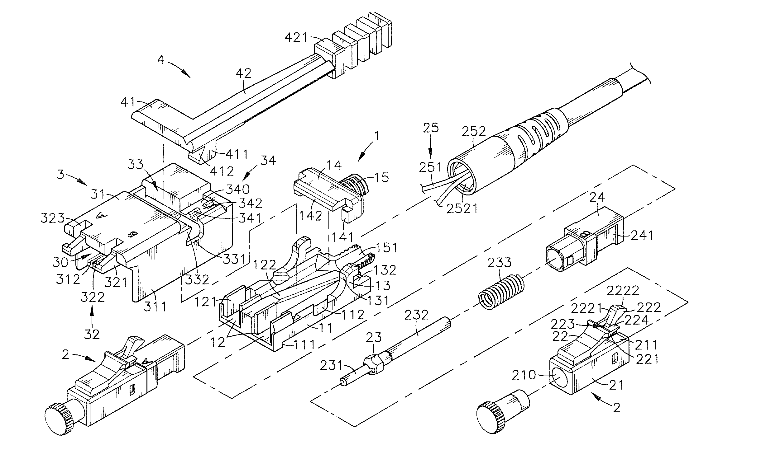
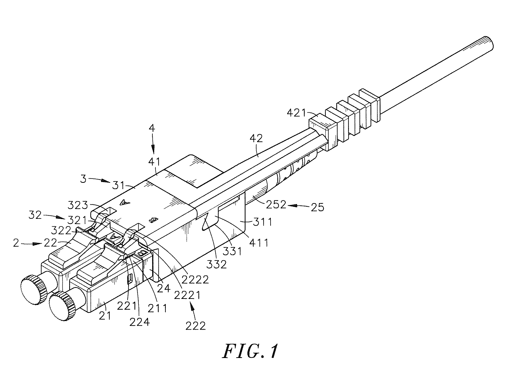
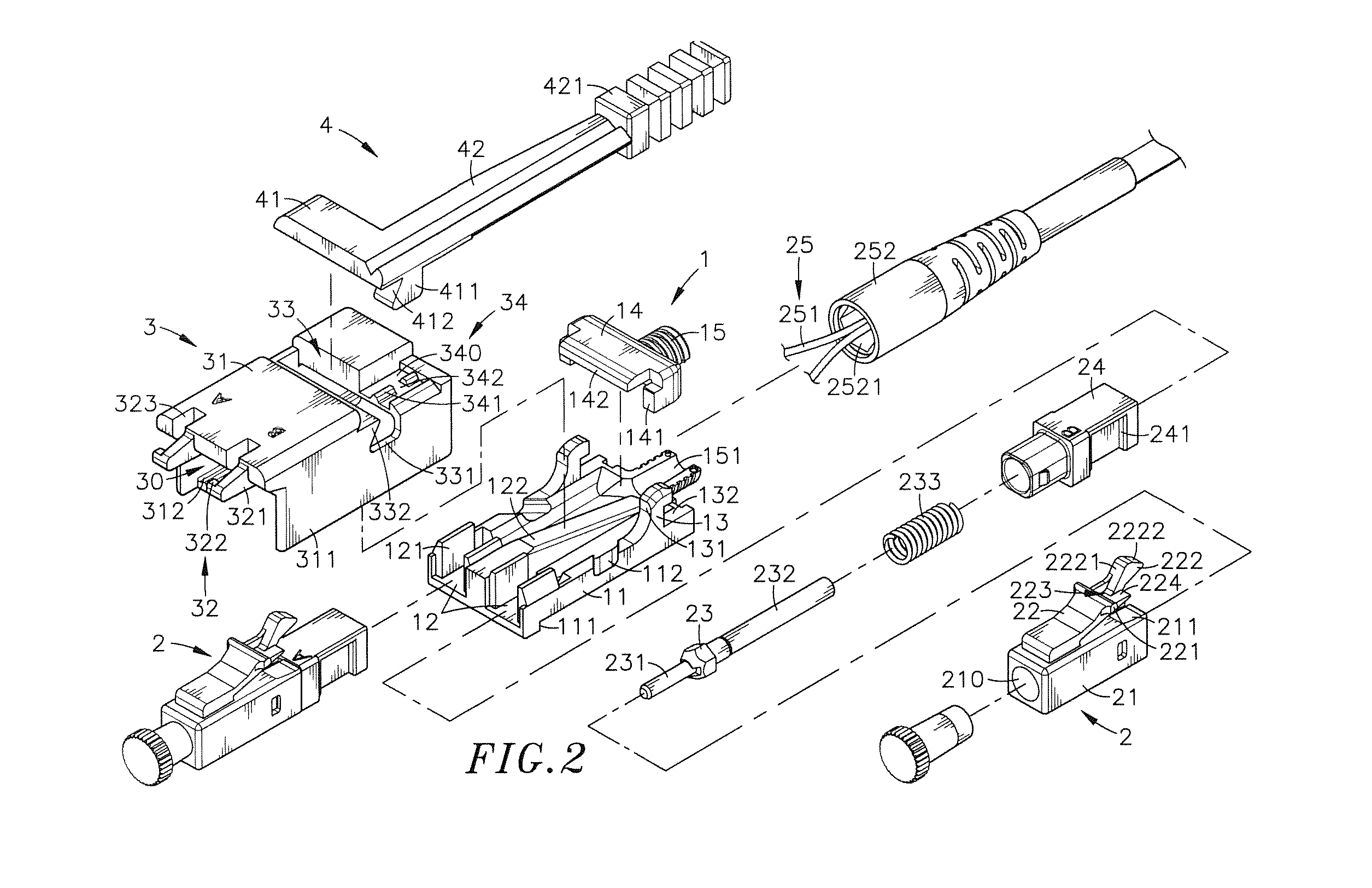
[0037]Referring to FIGS. 1-4, an optical fiber connector assembly in accordance with a first embodiment of the present invention is shown. The optical fiber connector assembly comprises a receptacle 1, at least one, for example, two connectors 2, a sliding cover 3, and an operating member 4.

[0038]The receptacle 1 comprises a body shell 11, a partition wall 122 defined inside the body shell 11 on the middle, two accommodation grooves 12 defined in the body shell 11 and separated by the partition wall 122 for accommodating the connectors 2 respectively, two pairs of upright hook blocks 121 respectively bilaterally disposed in respective front ends of the two accommodation grooves 12 in the body shell 11, two longitudinal sliding grooves 111 extending along two opposite lateral sides of a bottom wall of the body shell 11, two locating grooves 112 respectively obliquely located on two opposite upright sidewalls of the body shell 11 on the middle, two stop blocks 13 respectively located ...


PUM


Abstract

An optical fiber connector assembly includes a receptacle, two connectors accommodated in respective accommodation grooves in the receptacle and having a respective clip located at a top side thereof for engagement with a respective retaining groove in a mating optical fiber adapter, an optical fiber cable having two optical fibers respectively mounted in the connectors, and a sliding cover covered on the receptacle and movable relative to the receptacle to elastically deform the clips and to further disengage the clips from the respective retaining grooves of the optical fiber adapter for allowing removal of the optical fiber connector assembly out of the optical fiber adapter with less effort.

Description

[0001]This reference is based on Provisional Application Ser. #61 / 964,029, filed on Dec. 23, 2013, currently pending.BACKGROUND OF THE INVENTION [0002]1. Field of the Invention[0003]The present invention relates to optical fiber technology, and more particularly to an optical fiber connector assembly, which can be conveniently mounted in a mating optical fiber adapter or dismounted therefrom with one single hand with less effort.[0004]2. Description of the Related Art[0005]Following fast development of communication and internet technology, telephone and network facilities are for data transmission and real time communication, bringing great convenience to people. In a communication system, cables are used for transmitting electrical signal or optical signal. The transmission of optical signal is faster than the transmission of electrical signal. Optical fiber cables are commonly used for transmitting optical signal. Further, optical fiber cables have the advantages of strong anti-e...

Claims


Application Information

Patent Timeline
Patent Type & Authority Applications(United States)
IPC IPC(8): G02B6/38
CPCG02B6/3807G02B6/3879G02B6/26G02B6/3821G02B6/3849G02B6/387G02B6/3874G02B6/3878G02B6/3885G02B6/3893G02B6/3897G02B6/4292
Inventor LEE, JHIH-PINGLIN, YEN-HSU
Owner CORNING OPTICAL COMM LLC
Why Eureka
Try Eureka