Method and apparatus for controlling operation of redox flow battery
a technology of redox flow battery and control apparatus, which is applied in the direction of fuel cells, indirect fuel cells, electrochemical generators, etc., can solve the problems of considerable time in solving the problem of capacity reduction, reduce the capacity of the battery, so as to prevent the reduction of the effect of reducing the capacity of the redox flow battery and reducing the cost burden
- Summary
- Abstract
- Description
- Claims
- Application Information
AI Technical Summary
Benefits of technology
Problems solved by technology
Method used
Image
Examples
example 1
[0057]In Example 1, operating conditions of a redox flow battery using separator A are set as follows.
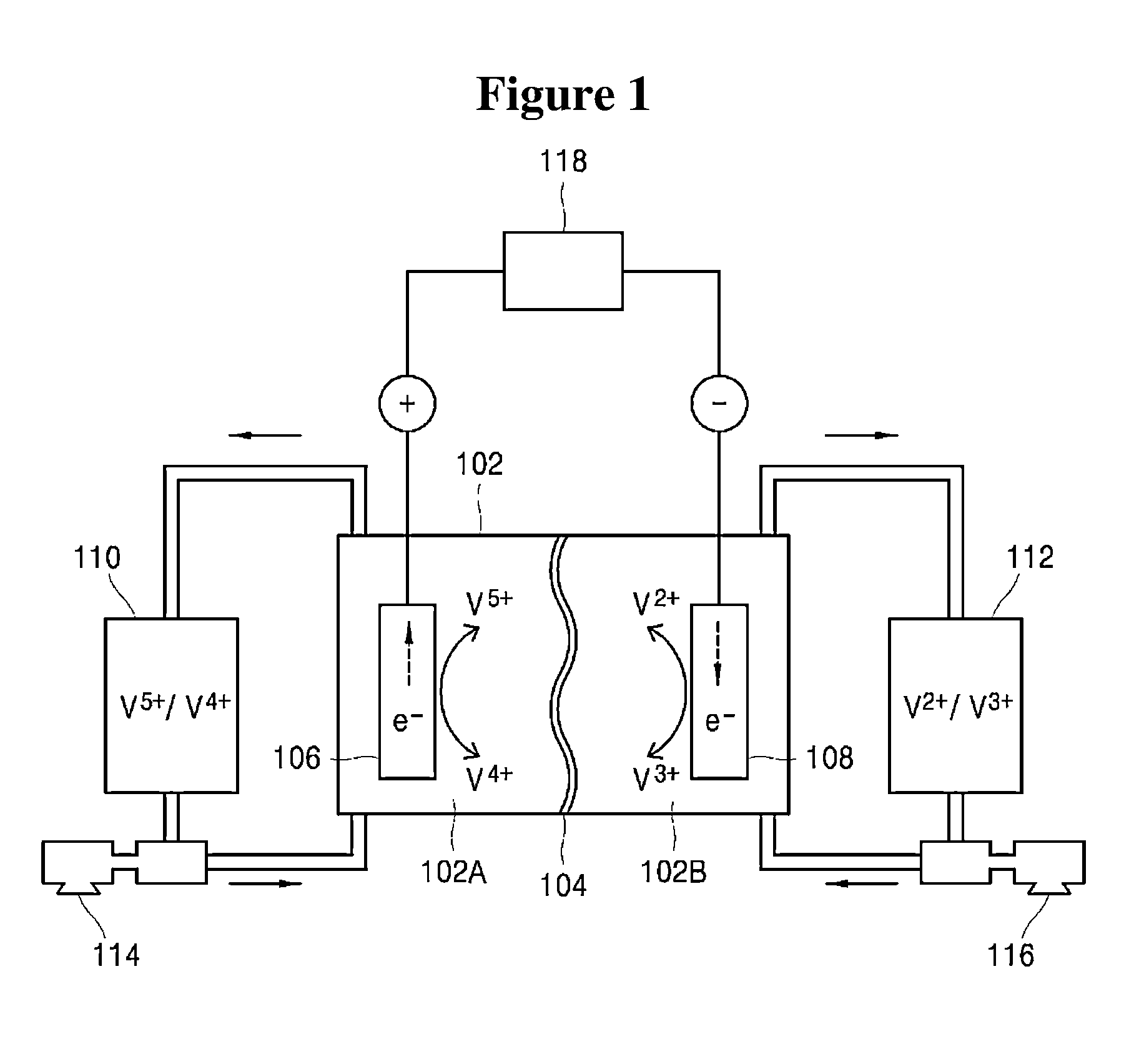
[0058]First, each of diffusivities of anolyte ions and catholyte ions with respect to the separator A is measured. Anolyte ions (V4+, V5+) and catholyte ions (V2+, V3+) have the following diffusivities with respect to the separator A, as measured by a method known in the art.[0059]Diffusivity of V2+ ions with respect to separator A: 2.7[0060]Diffusivity of V3+ ions with respect to separator A: 1.0[0061]Diffusivity of V4+ ions with respect to separator A: 2.1[0062]Diffusivity of V5+ ions with respect to separator A: 1.8
[0063]After obtaining such diffusivities of the anolyte ions and catholyte ions with respect to the separator A, the diffusivity determination unit 304 determines electrolyte diffusivities, that is, an anolyte diffusivity and a catholyte diffusivity, based on the diffusivity of the anolyte ions and the diffusivity of the catholyte ions obtained as above. Thereafter, th...
example 2
[0073]In Example 2, operating conditions of a redox flow battery using separator B are set as follows.
[0074]First, each of diffusivities of anolyte ions and catholyte ions with respect to the separator B is measured. Anolyte ions (V4+, V5+) and catholyte ions (V2+, V3+) have the following diffusivities with respect to the separator B, as measured by a method known in the art.[0075]Diffusivity of V2+ ions with respect to separator B: 1.0[0076]Diffusivity of V3+ ions with respect to separator B: 2.7[0077]Diffusivity of V4+ ions with respect to separator B: 1.8[0078]Diffusivity of V5+ ions with respect to separator B: 2.1
[0079]After obtaining such diffusivities of the anolyte ions and catholyte ions with respect to the separator B, the diffusivity determination unit 304 determines electrolyte diffusivities, that is, an anolyte diffusivity and a catholyte diffusivity, depending upon state of charge values according to Equation 1 and Equation 2, based on the diffusivity of the anolyte io...
example 3
[0088]In Example 3, operating conditions of a redox flow battery using NAFION 115 as a separator are set as follows.
[0089]First, each of diffusivities of anolyte ions and catholyte ions with respect to NAFION 115 is measured. Anolyte ions (V4+, V5+) and catholyte ions (V2+, V3+) have the following diffusivities with respect to NAFION 115, as measured by a method known in the art.
[0090]Diffusivity of V2+ ions with respect to NAFION 115: 6.4
[0091]Diffusivity of V3+ ions with respect to NAFION 115: 1.0
[0092]Diffusivity of V4+ ions with respect to NAFION 115: 2.6
[0093]Diffusivity of V5+ ions with respect to NAFION 115: 1.2
[0094]After obtaining such diffusivities of the anolyte ions and catholyte ions with respect to NAFION 115, the diffusivity determination unit 304 determines electrolyte diffusivities, that is, an anolyte diffusivity and a catholyte diffusivity, based on the diffusivity of the anolyte ions and the diffusivity of the catholyte ions obtained as above. Thereafter, the dif...
PUM
| Property | Measurement | Unit |
|---|---|---|
| state of charge | aaaaa | aaaaa |
| voltage | aaaaa | aaaaa |
| open circuit voltage | aaaaa | aaaaa |
Abstract
Description
Claims
Application Information
 - R&D
- Intellectual Property
- Life Sciences
- Materials
- Tech Scout
- Unparalleled Data Quality
- Higher Quality Content
- 60% Fewer Hallucinations
Browse by: Latest US Patents, China's latest patents, Technical Efficacy Thesaurus, Application Domain, Technology Topic, Popular Technical Reports.
© 2025 PatSnap. All rights reserved.Legal|Privacy policy|Modern Slavery Act Transparency Statement|Sitemap|About US| Contact US: help@patsnap.com


