
Systems and methods for correcting detector errors in computed tomography imaging

a computed tomography and detector error technology, applied in tomography, instruments, applications, etc., can solve problems such as material and electronics cannot keep, material and electronics are unable to keep up, and the detected signal is distorted dramatically

Active Publication Date: 2015-07-02
GENERAL ELECTRIC CO
View PDF0 Cites 14 Cited by
  • Summary
  • Abstract
  • Description
  • Claims
  • Application Information

AI Technical Summary

Benefits of technology

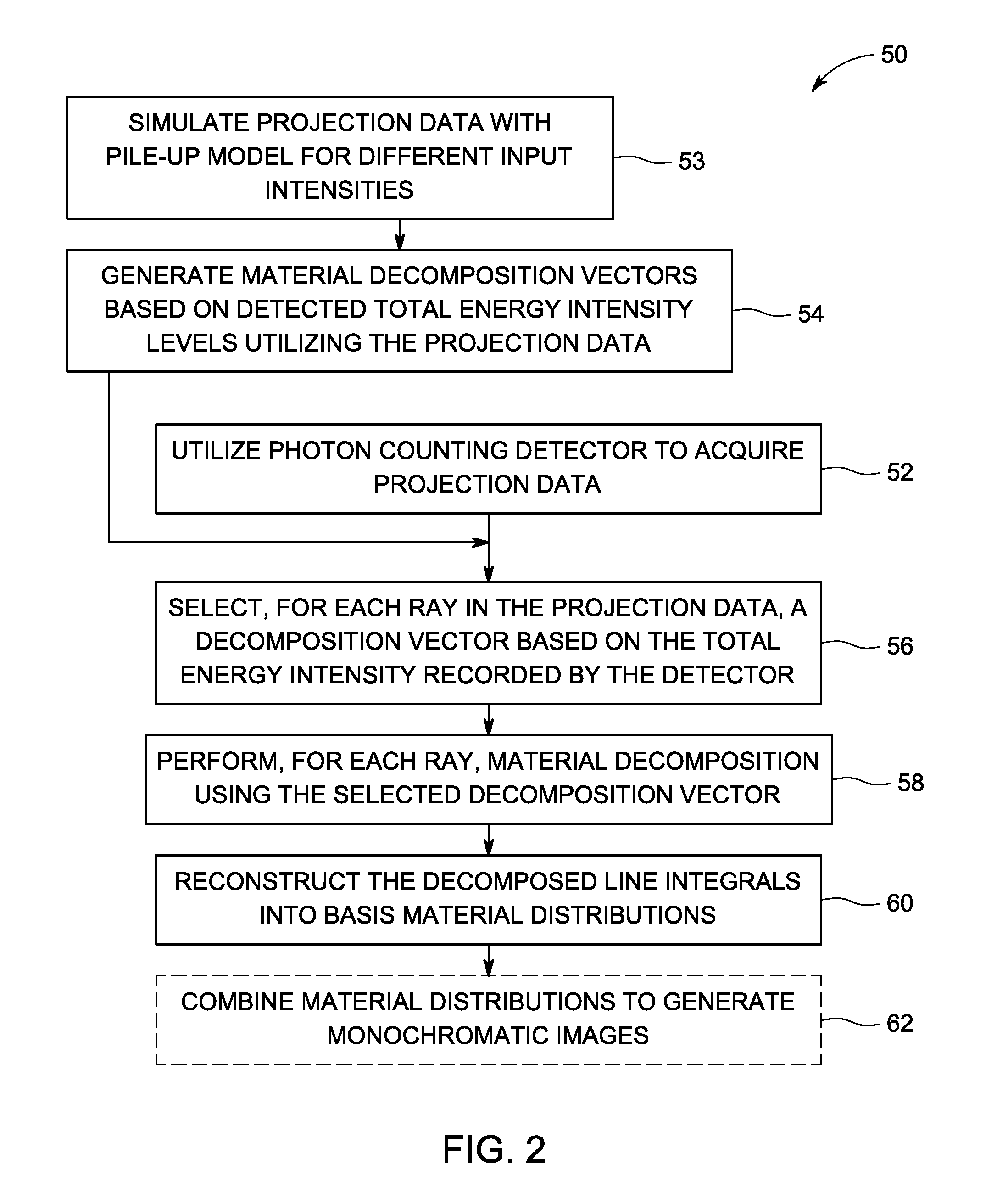
This patent describes a multi-energy computed tomography (CT) imaging system that uses an energy-discriminating, photon-counting X-ray detector to measure the energy of X-ray photons that reach the detector. The detector produces a signal that represents the total energy deposited during a data acquisition time period. The system also includes data processing circuitry that uses a detector pile-up model to simulate the count rate for each energy bin and determines a set of energy intensity dependent material decomposition vectors for each ray of X-ray photons. The system then performs material decomposition on the measured energy intensity of each ray by utilizing the simulated photon count rate and the corresponding material decomposition vector. The technical effect of this invention is the ability to accurately determine the energy of X-ray photons that reach the detector and perform material decomposition on the X-ray photons to improve the accuracy and accuracy of CT imaging.

Problems solved by technology

However, one obstacle impeding its clinical utility is the current count rate capability of this detector technology: the incident photon flux rate required for clinical CT imaging is beyond the counting capability of currently-available energy-discriminating, photon-counting detectors, thus giving rise to a pile-up effect that results in dramatic distortions in the detected signal.
The pile-up effect occurs when detector sensor material and electronics cannot keep pace with the incident X-ray flux rate.
The energy from multiple photons is deposited during a charge-integration interval in the detector; both the count and energy of detected photons are erroneous if the incident photon flux rate is too high.
While methods have been proposed to use the amplitude profile of the detected spectrum to generate a correction for pile-up effect, such methods do not account for the need to perform material decomposition often used for multi-energy imaging.

Method used


Image

  • Systems and methods for correcting detector errors in computed tomography imaging
  • Systems and methods for correcting detector errors in computed tomography imaging
  • Systems and methods for correcting detector errors in computed tomography imaging

Examples


Embodiment Construction

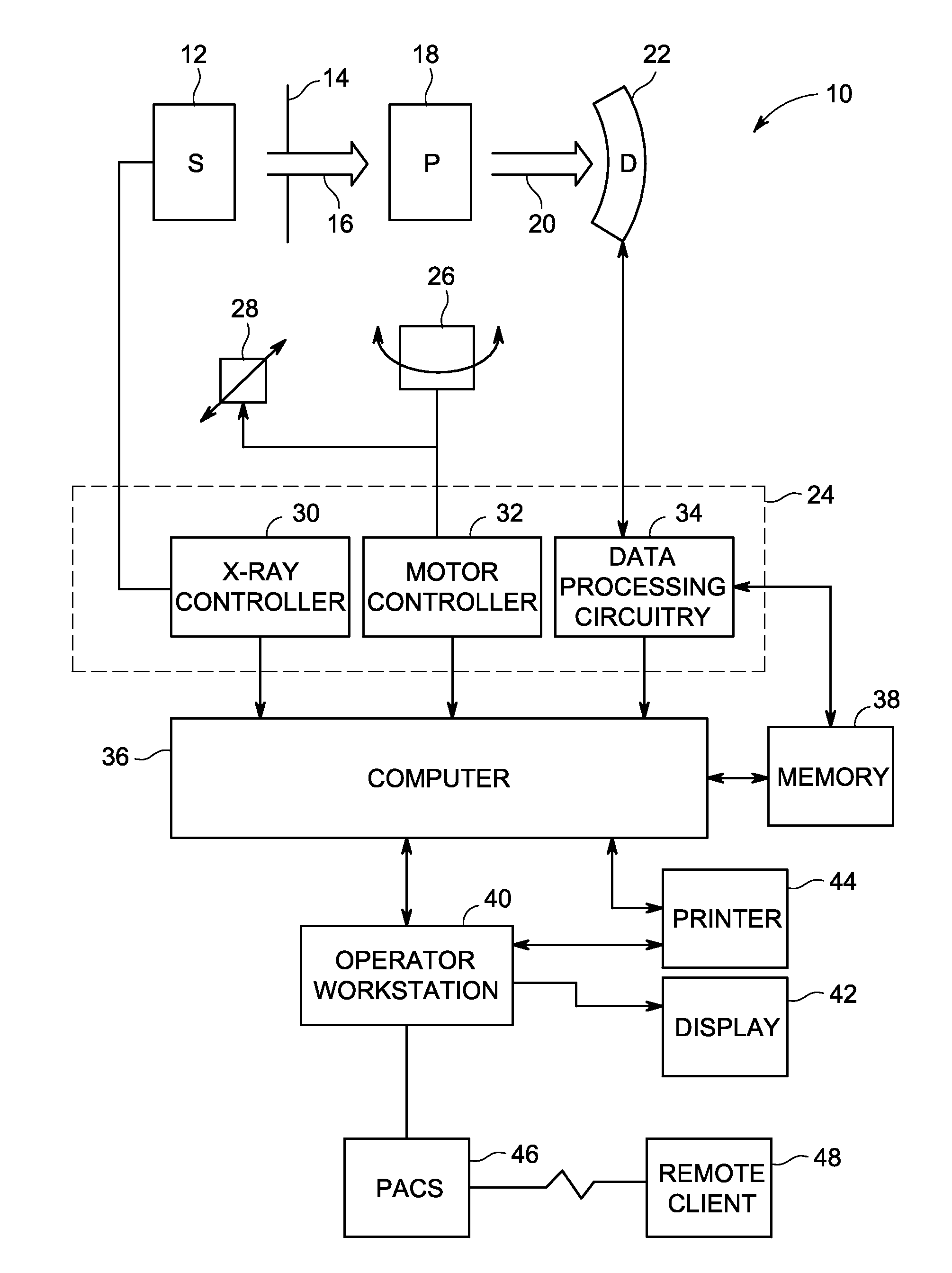
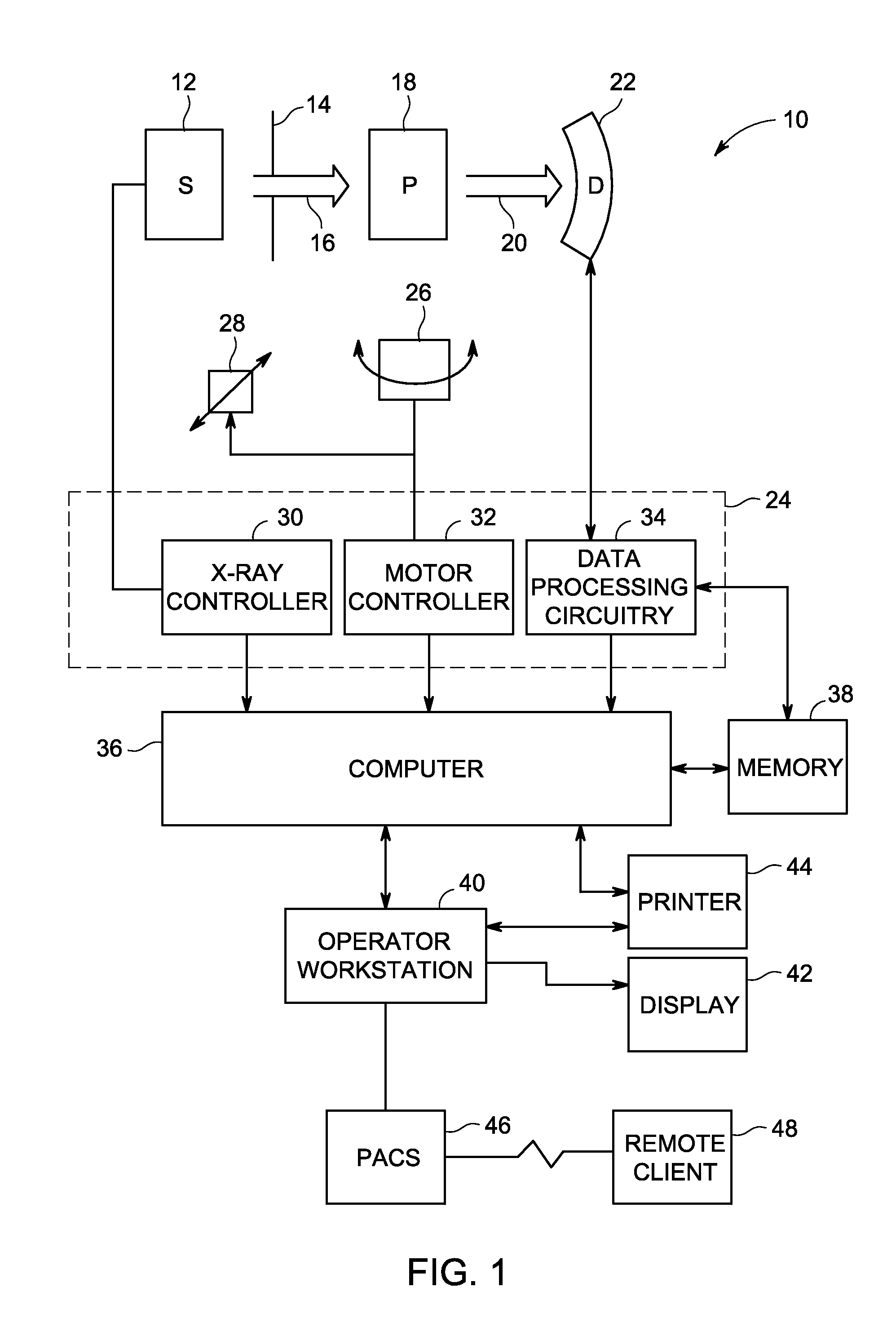
[0014]As described in more detail below, provided herein are systems and methods for combining detector pile-up correction and material decomposition in multi-energy X-ray imaging systems. Energy-discriminating, photon-counting detectors are widely recognized for their energy-discriminating capability, but their widespread clinical application has been impeded by the limited photon flux count rate capability that such detectors can accommodate. That is, the photon flux rate required to perform high-fidelity clinical computed tomography (CT) imaging exceeds the capabilities of the presently available energy-discriminating, photon-counting detectors. Even when the incident rate is a small fraction of the detector's maximum periodic count rate capability, a pile-up effect results in dramatic spectral distortions (both in terms of count and spectral shape) in the detected signal, thus presenting challenges for applying quantitative material decomposition methods as required in multi-ene...


PUM


Abstract

A system includes an energy-discriminating, photon-counting X-ray detector, comprising a plurality of detector cells providing measurements corresponding to at least two energy bins and being adapted to produce projection data in response to X-ray photons that reach the X-ray detector and to produce an electrical signal having a recorded count for the energy bins and a total energy intensity. The system also includes data processing circuitry adapted to receive the electrical signal from one or more of the plurality of detector cells, to generate a simulated count rate for each of the energy bins by using the total energy intensity in a detector pile-up model, to determine a set of energy intensity dependent material decomposition vectors, and, for the projection data measured by one or more of the plurality of detector cells, to perform material decomposition by modeling the simulated count rate for each of the energy bins and utilizing a material decomposition vector selected from the set of energy intensity dependent material decomposition vectors and corresponding to the measured energy intensity from one or more of the plurality of detector cells.

Description

BACKGROUND[0001]The subject matter disclosed herein generally relates to medical imaging systems and methods. More particularly, the disclosed subject matter relates to systems and methods for correcting errors arising due to a pile-up effect with energy-discriminating, photon-counting detectors when performing material decomposition.[0002]In modern medicine, medical professionals routinely desire to conduct patient imaging examinations to assess the internal condition of a patient in a non-invasive manner. For typical single-energy computed tomography (CT) imaging, the resulting X-ray images are largely a representation of the average density of each analyzed voxel based upon the patient's attenuation of X rays emitted by the X-ray source and detected by the X-ray detector. However, for multi-energy X-ray imaging, a greater amount of imaging data may be gleaned for each voxel, such as an estimate of the type of material in each analyzed voxel. For example, in a dual-energy X-ray im...

Claims


Application Information

Patent Timeline
IPC IPC(8): A61B6/00A61B6/03
CPCA61B6/4241A61B6/032A61B6/482G01T1/171
Inventor JIN, YANNANEDIC, PETER MICHAELLOBASTOV, VLADIMIR A.GAO, HEWEIFU, GENG
Owner GENERAL ELECTRIC CO
Learn More