Percutaneous access pathway system and method

a percutaneous access and pathway technology, applied in the field of medical devices, can solve the problems of long practice, damage to the underlying structure, and risk of laceration of the underlying organ, and achieve the effects of reducing friction and/or the chance of tissue pinching, reducing user error, and increasing and/or reducing the cross-sectional area of the catheter

a percutaneous access and pathway technology, applied in the field of medical devices, can solve the problems of long practice, damage to the underlying structure, and risk of laceration of the underlying organ, and achieve the effects of reducing friction and/or the chance of tissue pinching, reducing user error, and increasing and/or reducing the cross-sectional area of the catheter

US20150182733A1Active Publication Date: 2015-07-02CRITICAL INNOVATIONS

Image

  • Percutaneous access pathway system and method
  • Percutaneous access pathway system and method
  • Percutaneous access pathway system and method

Examples


Embodiment Construction

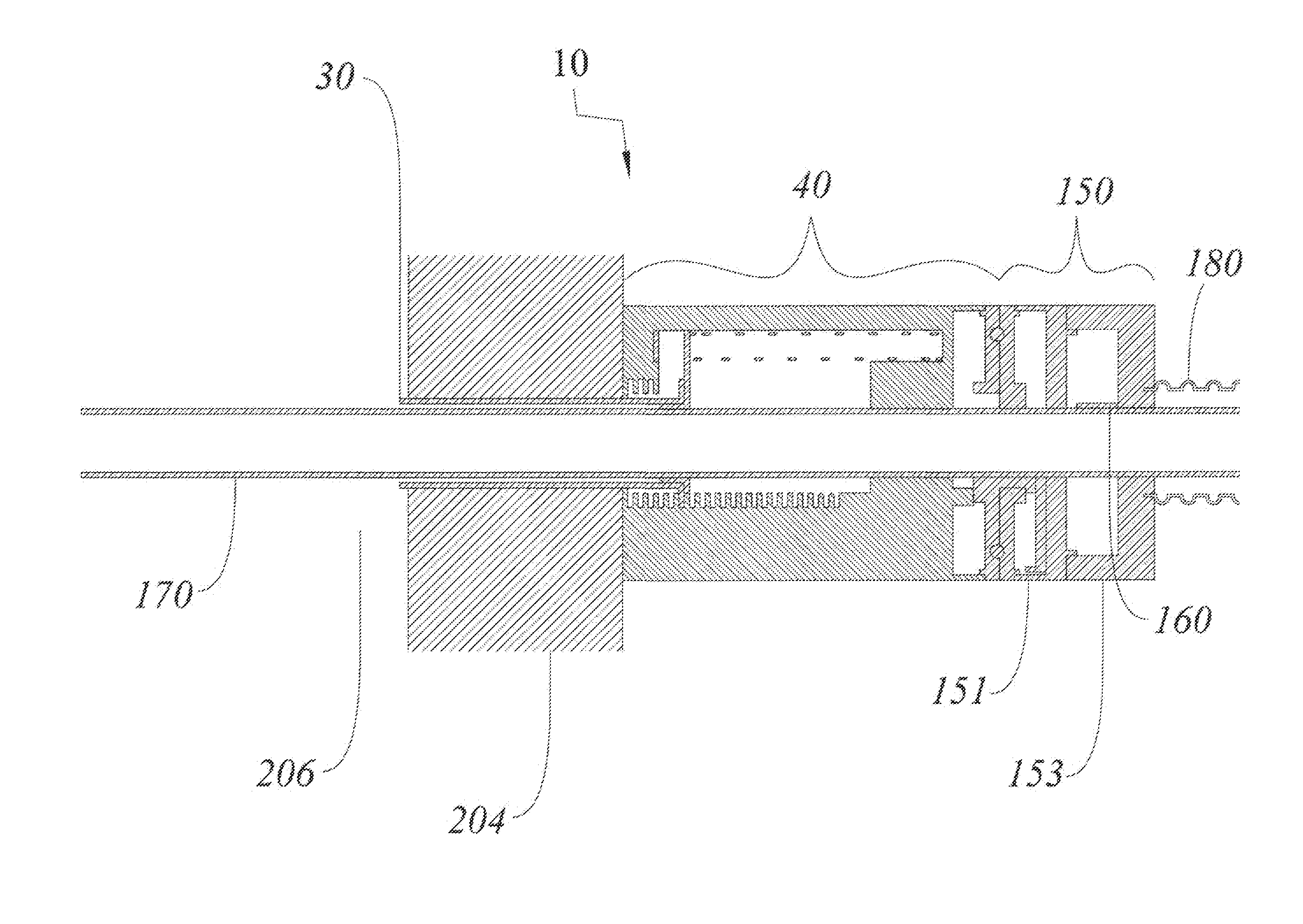
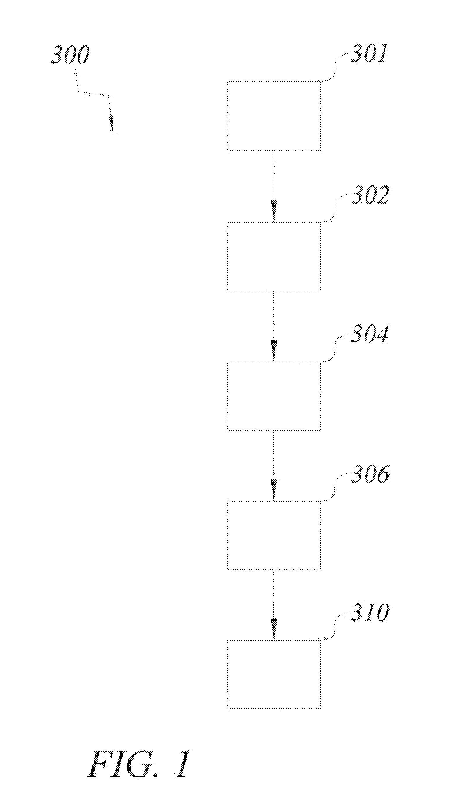
[0056]Referring to the drawings, FIG. 1 generally shows a method and workflow 300 according to an embodiment of the invention for forming and / or maintaining a percutaneous access pathway. This method and workflow 300 should be assumed to fit within standard emergency, pulmonary, and surgery protocols well known in the art (and not described here). Additionally, methods of standard needle use and safety, patient cleaning and sterilization, equipment disposal, suction setup and other standard medical practice well known in the art are not described here. The method 300 starts with providing a percutaneous access pathway at step 301. Under numerous embodiments, said access pathway includes a port and a catheter (i.e. an elongated tubular member). Under many but not all embodiments, said percutaneous access pathway also comes with an insertion device that includes a dilatational member. Under several embodiments, the dilatational member is initially positioned at least partially within ...


PUM


Abstract

An improved method and device are provided for forming and / or maintaining a percutaneous access pathway. The device generally comprises at least one of three type of components: access pathway, insertion device, and attachment device. In one embodiment, the device is used to form and / or maintain a percutaneous access pathway into the pleural cavity (i.e. tube thoracostomy). The provided assembly substantially reduces the possibility of iatrogenic infection while accessing and / or re-accessing a body space.

Description

RELATED APPLICATIONS[0001]The present application claims the benefit of U.S. Provisional Application No. 61 / 920,963 filed Dec. 26, 2013, which is incorporated herein in its entirety by reference. U.S. patent application Ser. No. 13 / 961,422, filed Aug. 7, 2013 and entitled Method and Device for Simultaneously Documenting and Treating Tension Pneumothorax and / or Hemothorax, having the same inventor as the present application, is also hereby incorporated by reference herein in its entirety.FIELD OF THE INVENTION[0002]The present disclosure relates generally to the field of medical devices, and more particularly, to devices and methods for forming and / or maintaining a percutaneous access pathway. In one application, the present invention relates to methods and devices for draining air and / or fluids from the body of a patient.BACKGROUND OF THE INVENTION[0003]A wide variety of diagnostic and / or therapeutic procedures involves the introduction of a device through a natural or artificially ...

Claims


Application Information

Patent Timeline
02 Jul 2015
Publication
US20150182733A1
IPC
A61M27/00; A61M1/04; A61M25/06; A61B17/34
CPC
A61M27/00; A61B17/3415; A61M2210/101; A61M25/0606; A61B17/3496; A61M1/04; A61B17/34; A61B2017/00809
Inventors
DONALDSON, ROSS I.