

Method of Producing Cold-Worked Centrifugal Cast Tubular Products
a centrifugal cast tubular and cold-worked technology, applied in the direction of pipes, mechanical equipment, metal rolling arrangements, etc., can solve the problems of limiting the choice of tubular components capable of withstanding the environment, grain size and casting defects, and higher temperatures and pressures in deeper wells
- Summary
- Abstract
- Description
- Claims
- Application Information
AI Technical Summary
Benefits of technology
Problems solved by technology
Method used
Image

Examples
Embodiment Construction
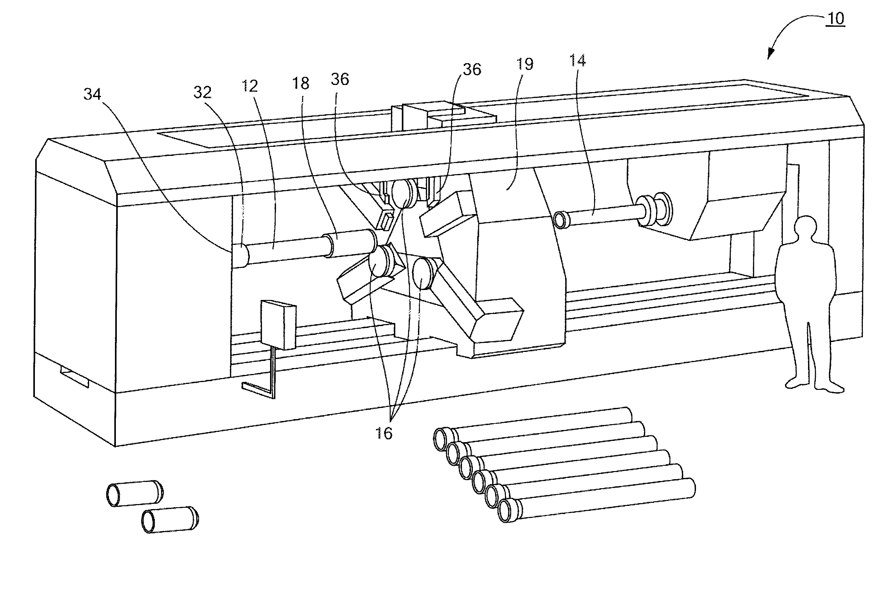
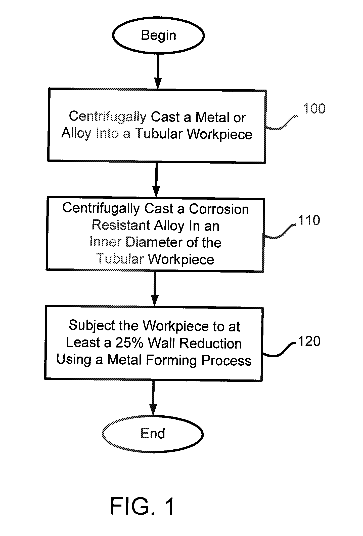
[0008]In accordance with one embodiment of the invention, a method of producing a seamless, composite tubular product includes centrifugally casting a metal or alloy into a tubular workpiece having an inner diameter. The method then centrifugally casts a corrosion resistant alloy in the inner diameter of the tubular workpiece to form a composite tubular workpiece having an inner diameter and an outer diameter, the inner diameter of the composite tubular workpiece formed of the corrosion resistant alloy and the outer diameter of the composite tubular workpiece formed of the metal or alloy. The method then subjects the composite tubular workpiece to at least about a 25% wall reduction at a temperature below a recrystallization temperature of the composite tubular workpiece using a metal forming process. The metal forming process includes radial forging, rolling, pilgering, and / or flowforming.
[0009]In some embodiments, the method further includes centrifugally casting one or more metal...
PUM
| Property | Measurement | Unit |
|---|---|---|
| inner diameter | aaaaa | aaaaa |
| corrosion resistant | aaaaa | aaaaa |
| temperature | aaaaa | aaaaa |
Abstract
Description
Claims
Application Information