Press die for electrically assisted manufacturing

a technology of press die and manufacturing technology, applied in the direction of presses, manufacturing tools, shaping tools, etc., can solve the problems of limited formability, hardly used in the industry, and high strength of ultra-high-strength materials

Active Publication Date: 2015-07-02
MYUNGSHIN IND CO LTD +3
View PDF7 Cites 17 Cited by
  • Summary
  • Abstract
  • Description
  • Claims
  • Application Information

AI Technical Summary

Benefits of technology

[0020]An object of the present invention is to provide a press die for electrically assisted manufacturing which includes an electrode for electrically assisted manufacturing to be able to prevent a current from leaking to a die or a working tool from a material at the time of the electrically assisted manufacturing.
[0026]In accordance with another aspect of the present invention, a press die for electrically assisted manufacturing performing forming at a relatively lower temperature than hot working by using an electroplasticity effect that a flow stress inside a material is reduced when a current is applied to the material, the press die for electrically assisted manufacturing includes: an upper die and a lower die configured to be disposed at upper and lower portions, having the material disposed therebetween; and at least one electrode pair configured to be disposed in the upper die or the lower die, wherein the electrode pair is configured so that electrodes having the same polarity in a width direction of the material face each other.

Problems solved by technology

However, the ultra high strength material has strength much higher than that of a general steel alloy or aluminum alloy and has limited formability under normal environment and therefore is hardly used in the industry.
However, these methods involves essential problems, such as a change in physical properties of a material, adhesion between a die and the material, a difficulty in lubrication, and time consumption required for heating and cooling, due to the material subjected to high temperature environment.
However, these state-of-the art technologies have variously technical advantages, but are not yet completely satisfactory.
The main reason is that initial cost of manufacturing equipments is high and it takes much time for a manufacturing process.
Meanwhile, as the die of a metal material or a working tool contacts the material at the time of forming the products using the electroplasticity effect, a supplied current may be leaked to the die or the working tool through the material.
As described above, when the current supplied to the material is leaked to the die or the working tool, a current distribution, such as a current density of the material, is changed, such that a quality of the formed products may not be insured or it is difficult to obtain a desired forming load.
Further, manufacturing cost may be increased due to wasted energy and the failure of equipment or the electric shock accident may occur due to the leakage current.

Method used


Image

  • Press die for electrically assisted manufacturing
  • Press die for electrically assisted manufacturing
  • Press die for electrically assisted manufacturing

Examples


first embodiment

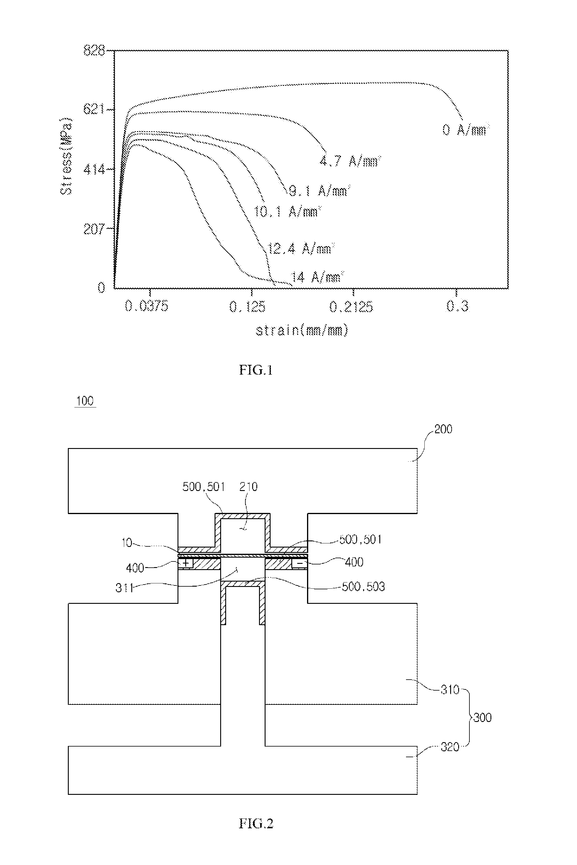
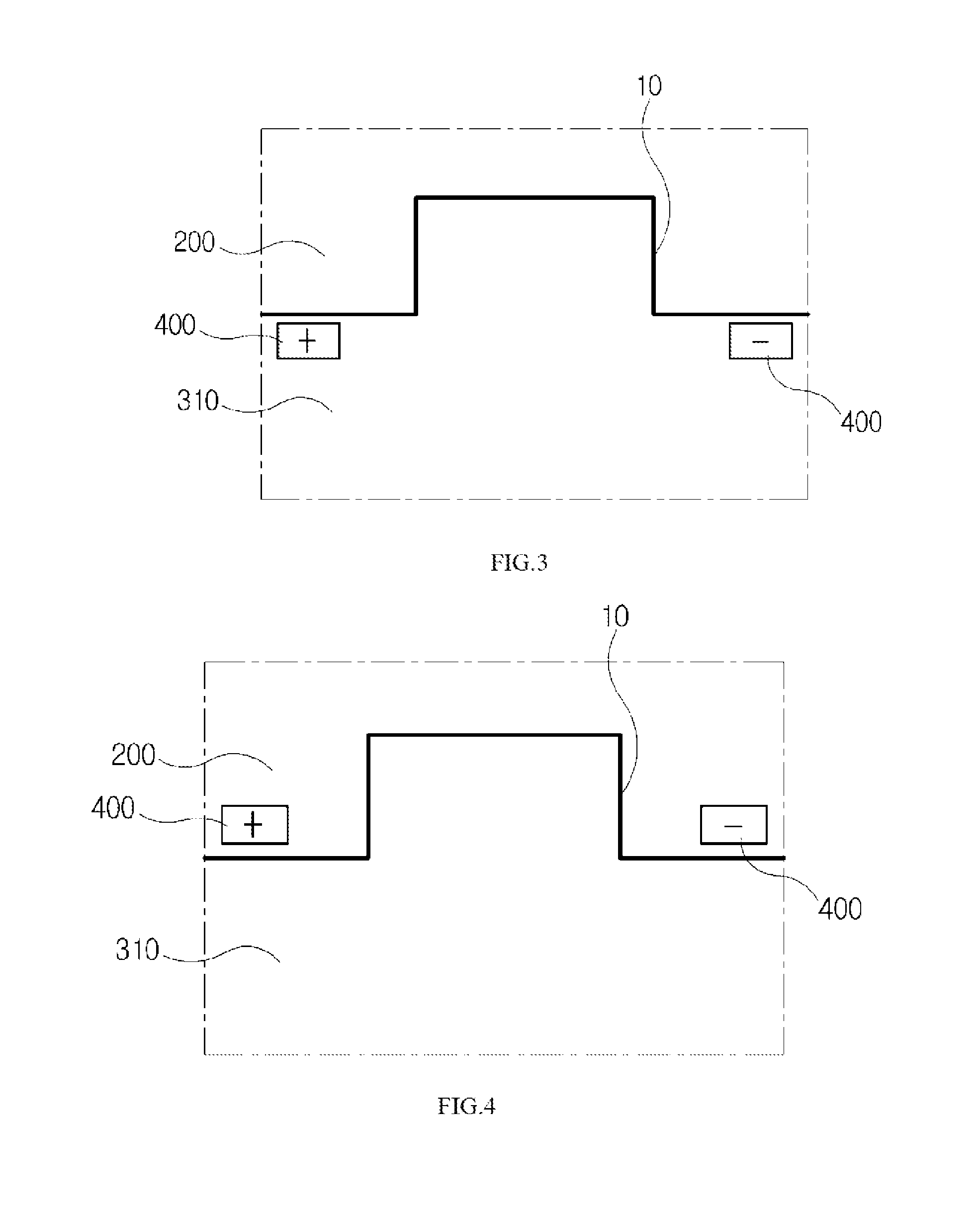
[0063]FIG. 2 is a schematic diagram of a press die for electrically assisted manufacturing in accordance with a first embodiment of the present invention and FIG. 3 is a schematic diagram illustrating a disposition structure of an electrode in accordance with the first embodiment of the present invention, in which for convenience of explanation, only relative positions of a material and electrode pairs are illustrated.

[0064]As illustrated in FIG. 2, a press die for electrically assisted manufacturing in accordance with a first embodiment of the present invention includes an upper die 200 and a lower die 300 disposed at upper and lower portions, having a material disposed therebetween.

[0065]In this case, the upper die 200 and the lower die 300 have a shape corresponding to a shape of a final product so that they may relatively move to each other to press a material 10 so as to be formed in a desired shape and a configuration of the upper die 200 and the lower die 300 may be variously...

second embodiment

[0094]FIG. 4 is a schematic diagram illustrating a disposition structure of an electrode in accordance with a second embodiment of the present invention, in which for convenience of explanation, only the relative positions of the material and the electrode pairs are illustrated.

[0095]The second embodiment of the present invention is substantially the same as the configuration of the first embodiment of the present invention described with reference to FIGS. 2 and 3, but has a difference from the configuration of the first embodiment of the present invention in that the electrode pairs are disposed in the upper die 200.

[0096]Therefore, the same components having the same functions as the first embodiment of the present invention as described above are denoted by the same reference numerals and the overlapping description thereof will be omitted.

third embodiment

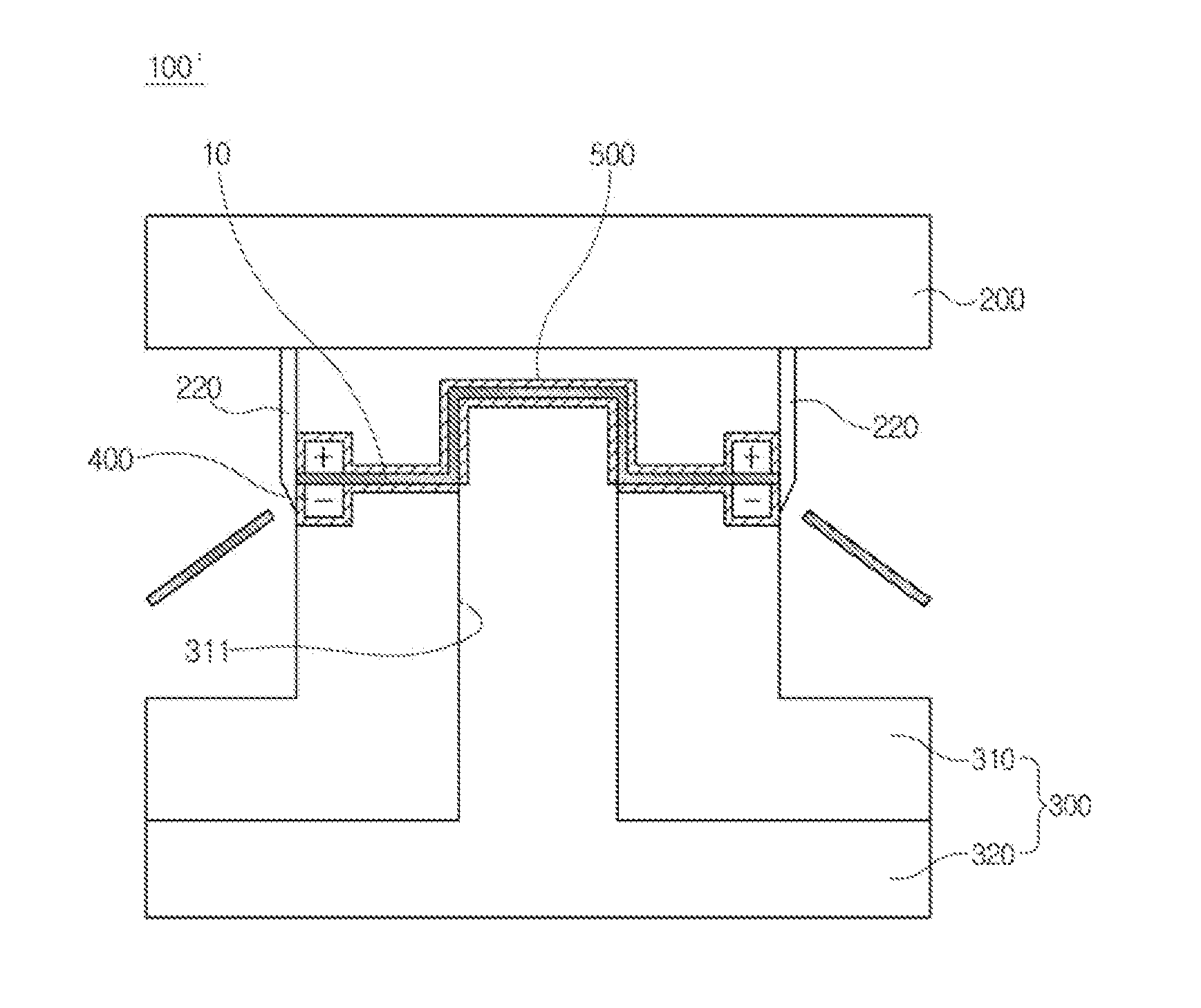
[0097]FIG. 5 is a schematic diagram illustrating a disposition structure of an electrode in accordance with a third embodiment of the present invention, in which for convenience of explanation, only the relative positions of the material and the electrode pairs are illustrated.

[0098]In accordance with the third embodiment of the present invention, both of the upper die 200 and the lower die 300 are each provided with the electrode pairs.

[0099]That is, the electrodes 400 having first polarity are disposed in the upper die 200 and the blank holder 310 along one edge in the width direction of the material 10 and the electrodes 400 having second polarity are disposed in the upper die 200 and the blank holder 310 along the other edge in the width direction of the material 10.

[0100]In this case, the electrodes 400 which are disposed in the upper holder 200 and the blank holder 310 to face each other in a thickness direction of the material have the same polarities. In this case, a flow of...


PUM

PropertyMeasurementUnit
temperatureaaaaaaaaaa

Abstract

The invention discloses a press die for electrically assisted manufacturing performing plastic working at a relatively lower temperature than hot working by using an electroplasticity effect that a flow stress inside a material is reduced when a current is applied to the material, the press die for electrically assisted manufacturing comprising: an upper die and a lower die configured to be disposed at upper and lower portions, having the material disposed therebetween; and at least one electrode pair configured to be disposed in the upper die or the lower die, wherein the electrode pair is configured so that electrodes having different polarities in a width direction of the material face each other.

Description

CROSS-REFERENCE TO RELATED APPLICATION(S)[0001]This application claims priority to Korean Patent Application Nos. 10-2013-0168468 and 10-2013-0168469, filed on Dec. 31, 2013, the disclosures of which are incorporated herein by reference in their entirety.BACKGROUND OF THE INVENTION[0002]1. Field of the Invention[0003]Exemplary embodiments of the present invention relate to a press die, and more particularly, to a press die for electrically assisted manufacturing which is used to work a material using an electroplasticity effect.[0004]2. Description of the Related Art[0005]Recently, an automobile industry has focused on a lightweight so as to improve fuel efficiency and tends to use ultra high strength car body parts so as to secure sufficient rigidity.[0006]That is, to form products having a relatively smaller weight and higher rigidity, a tendency to fold the products using a higher strength material has increased.[0007]However, the ultra high strength material has strength much hi...

Claims


Application Information

Patent Timeline
Patent Type & Authority Applications(United States)
IPC IPC(8): B21D37/16H05B3/00
CPCH05B3/0004B21D37/16B21D22/208B21D24/16B30B15/34
Inventor KIM, JANG-SOOYANG, DAE-HOJIN, HONG-KYOKIM, KYUNG-SIKKWEON, DONG-KEUNSO, SANG-WOOHWANG, HYUN-TAE
Owner MYUNGSHIN IND CO LTD
Why Eureka
Try Eureka