Trailing arm bush for coupled torsion beam axle

a technology of torsion beam axle and trailing arm bush, which is applied in the direction of interconnection systems, resilient suspensions, vehicle components, etc., can solve the problems of lowering the comfort of the vehicle to induce impact harshness, the difficulty in optimizing the trailing arm bush for ctba, and the disadvantage of the vehicle's handling and durability of the bush, so as to improve the handling and riding comfort of the vehicle, and the occurrence of abnormal noise significantly reduced

Active Publication Date: 2015-07-02
HYUNDAI MOTOR CO LTD +1
View PDF22 Cites 4 Cited by
  • Summary
  • Abstract
  • Description
  • Claims
  • Application Information

AI Technical Summary

Benefits of technology

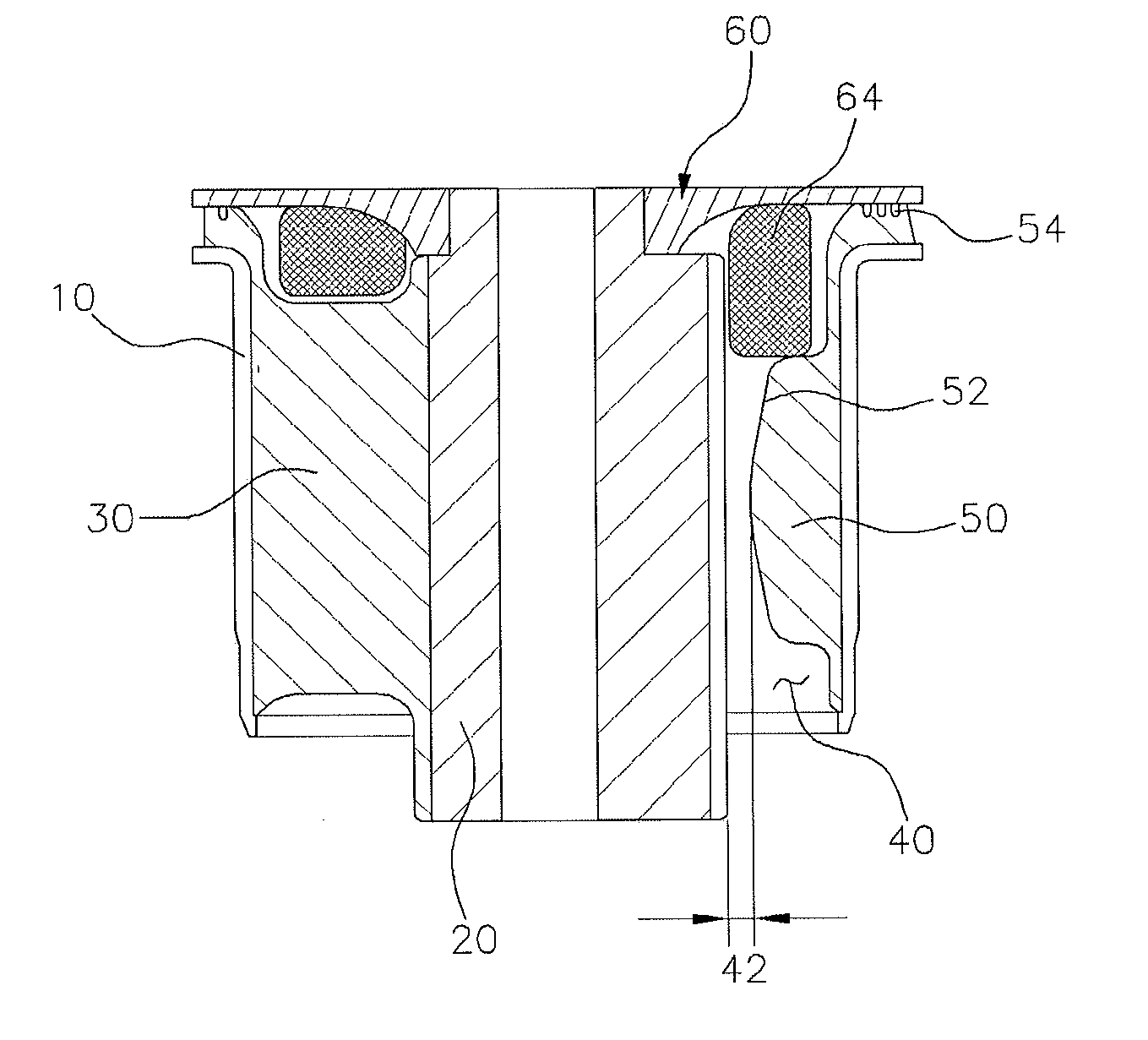
[0020]Various aspects of the present invention are directed to providing a trailing arm bush for CTBA in which both handling and riding comfort of the vehicle are improved and the occurrence of abnormal noise is significantly reduced, by developing a three-bridge type trailing arm bush for CTBA in which a shape of a bush rubber unit for connecting between the outer pipe and the inner pipe is changed and an external stopper is mounted to one end of the inner pipe.
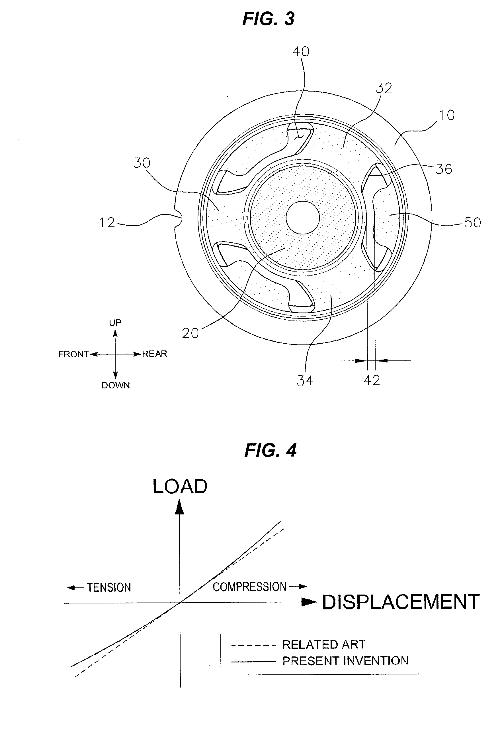
[0029]That is, since the bush rubber unit is formed symmetrically on the basis of the inner pipe, the conventional trailing arm bush for CTBA has characteristics of a linear spring, and thus, it is not possible to satisfy both handling and riding comfort of the vehicle. Meanwhile, since the bush rubber unit is formed asymmetrically on the basis of the inner pipe, the trailing arm bush for CTBA according to the present invention can have characteristics of a non-linear spring, and thus, there is an effect of being able to satisfy both handling and riding comfort.
[0030]Therefore, the trailing arm bush for CTBA according to the present invention is able to prevent the prolonged development period of the trailing arm bush for CTBA according to the excessive number of tests, and prevent the consumption of the excessive development costs in development of the trailing arm bush for CTBA.
[0031]Further, there is an effect of significantly reducing the occurrence of abnormal noise, by securing a maximum separation distance between the outer peripheral surface of the inner pipe and the stopper to limit the role of the stopper to large displacement prevention.

Problems solved by technology

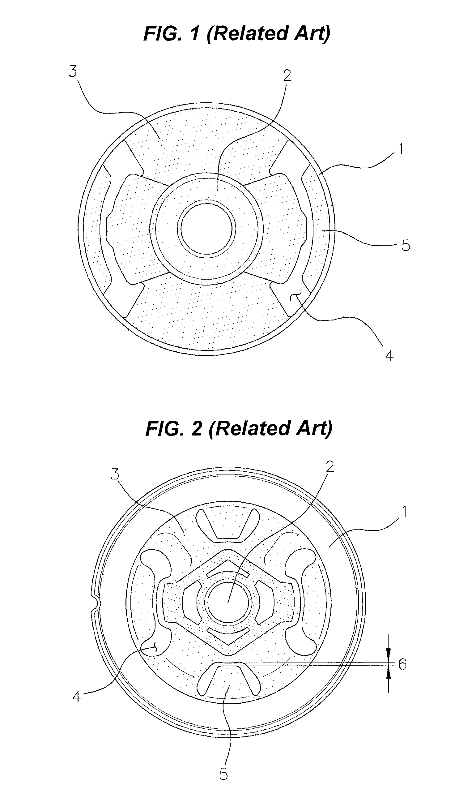
As shown in FIG. 1, a so-called two-bridge type trailing arm bush for CTBA configured to connect two parts between the outer pipe 1 and the inner pipe 2 has good characteristics in terms of handling of the vehicle and durability of the bush, but there is a disadvantage in that riding comfort of the vehicle is lowered to induce Impact harshness.
Meanwhile, as shown in FIG. 2, a so-called four-bridge type trailing arm bush for CTBA configured to connect four parts between the outer pipe 1 and the inner pipe 2 has an advantage in that the riding comfort is excellent as compared to the two-bridge type, but has a disadvantage in terms of handling of the vehicle and durability of the bush.
That is, since handling and riding comfort of the vehicle are inversely proportional to the trailing arm bush for CTBA, there is a need for trade-off between two characteristics at the time of actual design, but there is a problem in that it is very difficult to optimize the trailing arm bush for CTBA while satisfying both two characteristics.
Thus, there are problems such as prolonged development period and consumption of extra development costs due to the extra number of tests, when developing a trailing arm bush for CTBA depending on the design of the conventional trailing arm bush for CTBA.
Furthermore, as shown in FIG. 2, since the conventional trailing arm bush for CTBA is primarily designed so that a very small gap 6 of 0.5 mm is formed between the stopper 5 and the inner pipe 2, and the four-bridge type trailing arm bush for CTBA has the spring characteristics of the six-bridge type, there is a problem in that a lot of abnormal noises occur.

Method used


Image

  • Trailing arm bush for coupled torsion beam axle
  • Trailing arm bush for coupled torsion beam axle
  • Trailing arm bush for coupled torsion beam axle

Examples


Embodiment Construction

[0046]Reference will now be made in detail to various embodiments of the present invention(s), examples of which are illustrated in the accompanying drawings and described below. While the invention(s) will be described in conjunction with exemplary embodiments, it will be understood that the present description is not intended to limit the invention(s) to those exemplary embodiments. On the contrary, the invention(s) is / are intended to cover not only the exemplary embodiments, but also various alternatives, modifications, equivalents and other embodiments, which may be included within the spirit and scope of the invention as defined by the appended claims.

[0047]Exemplary embodiments of a door outside handle for vehicle according to an exemplary embodiment of the present invention will be described hereafter in detail with reference to the accompanying drawings.

[0048]Hereinafter, the present invention will be described in detail with reference to the accompanying drawings to allow t...


PUM


Abstract

A trailing arm bush may include a cylindrical outer pipe, an inner pipe inserted to a central portion of the outer pipe at an interval, a first bush rubber unit, a second bush rubber unit and a third bush rubber unit that connect between an inner peripheral surface of the outer pipe and an outer peripheral surface of the inner pipe, respectively, a hollow void part formed between the inner peripheral surface of the outer pipe and the outer peripheral surface of the inner pipe, and a stopper attached to the inner peripheral surface of the outer pipe and disposed among the first bush rubber unit, the second bush rubber unit and the third bush rubber unit.

Description

CROSS-REFERENCE TO RELATED APPLICATION[0001]The present application claims priority to Korean Patent Application No. 10-2013-167984 filed on Dec. 31, 2013, the entire contents of which is incorporated herein for all purposes by this reference.BACKGROUND OF THE INVENTION[0002]1. Field of the Invention[0003]The present invention relates to a trailing arm bush for CTBA that connects between a pair of trailing arms supported by a torsion beam disposed in a vehicle width direction and a vehicle body, and more particularly, to a trailing arm bush for CTBA in which by forming three bush rubber units for connecting between an inner peripheral surface of an outer pipe and an outer peripheral surface of the inner pipe, a bush rubber unit can have characteristics of a non-linear spring when the inner pipe moves back and forth by external vibration of the vehicle, and a gap between the inner pipe and a stopper is secured to significantly improve an abnormal noise generation phenomenon.[0004]2. ...

Claims


Application Information

Patent Timeline
Patent Type & Authority Applications(United States)
IPC IPC(8): B60G21/05
CPCB60G21/051B60G21/052B60G2200/20B60G2204/1434B60G2204/41B60G2204/41042
Inventor KIM, SANG-RAKLIM, JUNG-TAEKHWANG, CHUL-HAYOUN, KYONG-SIK
Owner HYUNDAI MOTOR CO LTD
Why Eureka
Try Eureka