Vehicle transmission controller

a technology of transmission controller and transmission shaft, which is applied in the direction of mechanical equipment, digital data processing details, instruments, etc., can solve the problems risk of deterioration of vehicle drivability, and motion equations that do not consider the engine as a controlled object, so as to reduce the risk of tie-up or racing phenomenon, reduce the output torque, and improve the effect of control

Active Publication Date: 2015-07-02
TOYOTA JIDOSHA KK
View PDF2 Cites 16 Cited by
  • Summary
  • Abstract
  • Description
  • Claims
  • Application Information

AI Technical Summary

Benefits of technology

[0007]According to the first aspect of the invention described above, the torque assignment ratios which are the ratios of the torques of the coupling devices to be respectively engaged and released are used as a restricting condition which should be satisfied to permit determination of the three manipulated amounts for establishing the two shifting target values. Accordingly, it is possible to adequately control a torque transfer between the coupling devices to be engaged and released (namely, a progress of the shifting action) during shifting, which would otherwise be considered difficult, and possible to determine the three manipulated amounts. Described in a different way, where one of the three manipulated amounts is set to be a predetermined certain value to determine the three manipulated amounts, this predetermined value should be selected from a large number of values corresponding to respective different shifting actions, for instance. According to the present invention, the torque assignment ratios representative of the torque transfer are set as the restricting condition, so that only one shifting model can deal with all of the different shifting actions. Described more specifically, if one of the torque capacity of the coupling device to be engaged and the torque capacity of the coupling device to be released is used as the restricting condition, there is a risk of occurrence of a tie-up phenomenon or a racing phenomenon of a rotary member. In the present invention, however, the torque assignment ratios suitable for controlling the progress of the shifting action are used as the restricting condition, so that it is possible to reduce a risk of occurrence of the tie-up or racing phenomenon, or to improve ease of control to be implemented for positively causing the tie-up or racing phenomenon to the contrary. If the torque of the rotary member disposed on the side of the input shaft is used as the restricting condition, there is a risk of failure to implement a control for temporarily changing the output torque of a drive power source. In the present invention, it is possible to adequately implement a torque reduction control for temporarily reducing the output torque of the drive power source in an inertia phase of the shifting action. Thus, the present invention permits adequate determination of the three manipulated amounts according to the shifting model, and a desired shifting control of the automatic transmission so as to establish the two shifting target values, although the three manipulated amounts are used for the two shifting target values.
[0008]According to a second aspect of the invention, the shift control apparatus according to the first aspect of the invention is configured such that the above-described shifting model is formulated to calculate the above-described manipulated amounts on the basis of the above-described shifting target values, and according to motion equations of the automatic transmission, and a relationship representative of the above-described torque assignment ratios, the motion equations including the above-described shifting target values and the above-described manipulated amounts. According to this second aspect of the invention, the three manipulated amounts can be adequately determined according to the above-indicated motion equations formulated to implement the control of the torque transfer during the shifting action, which would otherwise be considered difficult.
[0009]According to a third aspect of the invention, the shift control apparatus according to the first or second aspect of the invention is configured such that the torque capacity of each of selected at least one of the above-described coupling devices to be respectively engaged and released is determined on the basis of the torque assignment ratio which includes an added tie-up amount. If the manipulated amount in the form of the torque capacity of one of the coupling devices to be released and engaged is zero upon a considerable change of the shifting target value at a moment of initiation or termination of the inertia phase of the shifting action, there is a risk of increase of the shifting shock due to abrupt changes of the actual values of the torque of the rotary member on the side of the output shaft and the rate of change of the rotary member on the side of the input shaft, with respect to the target values, which abrupt changes are caused by delayed changes or variations of the actual values of the manipulated amounts in the form of the torque capacities of the coupling devices with respect to the required values. According to this third aspect of the invention, the torque transfer between the coupling devices is controlled so as to cause the tie-up phenomenon, whereby the torque transfer can be smoothly implemented, with each selected coupling device absorbing an abrupt change of the transmission output torque, making it possible to reduce the shifting shock which would have a risk of increase upon a considerable change of the shifting target values.
[0010]According to a fourth aspect of the invention, the shift control apparatus according to the third. aspect of the invention is configured such that the above-described each of selected at least one of the above-described coupling devices does not have a speed difference. According to this fourth aspect of the invention, the torque capacity of each selected coupling device increased to cause the tie-up phenomenon does not increase the transmission torque, that is, does not have an influence on the actual value of the torque of the rotary member on the side of the output shaft, in the phase other than the inertia phase.
[0011]According to a fifth aspect of the invention, the shift control apparatus according to the third or fourth aspect of the invention is configured such that the above-described tie-up amount is increased with a decrease of an amount of torque reduction by the drive power source in an inertia phase of the shifting action of the above-described automatic transmission, or with an increase of a delay in a response of the torque reduction. According to this fifth aspect of the invention, the torque transfer between each selected coupling device is controlled so as to increase the degree of causing the tie-up phenomenon with an increase of the amounts of change of the shifting target values, or with an increase of the degree of likelihood of abrupt change of the actual values of the shifting target values, making it possible to more effectively reduce the shifting shock.
[0012]According to a sixth aspect of the invention, the shift control apparatus according to any one of the third through fifth aspects of the invention is configured such that the shifting control of the above-described automatic transmission according to the above-described shifting model in an inertia phase is implemented by reversing a sign of the torque assignment ratio which is used to determine the torque capacity of the above-described each selected coupling device, the torque assignment ratio including the above-described added tie-up amount. According to this sixth aspect of the invention, which is based on a finding that there is a risk of failure to establish the shifting target values in the inertia phase where the torque assignment ratio includes the added tie-up amount, the sign of the torque assignment ratio of the relevant coupling device in the inertia phase is reversed such that the sign is coincident with the direction of the torque actually generated by the relevant coupling device, so that the manipulated amounts can be determined so as to permit the shifting target values to be established in the practical inertia phase, while permitting a smooth torque transfer between the coupling devices, whereby the shifting action can be performed in a desired manner.

Problems solved by technology

However, these techniques disclosed in the Patent Document 1 may suffer from deterioration of drivability of the vehicle due to a relatively long time required for completion of a shifting action of the automatic transmission, because a hydraulic pressure of a coupling device to be released for the shifting action is first lowered for a releasing action of the coupling device, and is then temporarily raised for an engaging action of the coupling device, in order to offset an inertia torque in the inertia phase (in other words, in order to prevent a substantial change of the torque of the output shaft in the inertia phase).
According to the techniques disclosed in the above-identified Patent Document 1, however, the motion equations do not consider the engine as a controlled object.
That is, according to the techniques disclosed in the Patent Document 1, the motion equations are solved with respect to a certain value of the engine torque, so that the shifting model control disclosed in the Patent Document 1 does not permit offsetting of the inertia torque by the engine torque reduction control implemented in place of the temporary rise of the hydraulic pressure of the coupling device to be released for the shifting action.
Although the engine torque reduction control may be implemented in addition to the shifting model control, the engine torque reduction control disturbs the shifting model control as a whole, leading to a need for solving again the motion equations, and a consequent requirement for a considerably long time for completion of the shifting action, and a risk of deterioration of the vehicle drivability due to an increase of the shifting shock.
If the engine torque is also determined uniquely as a manipulated amount according to the shifting model control, on the other hand, three manipulated amounts are used for two shifting target values, so that the motion equations cannot be solved, resulting in a failure of the shifting action of the automatic transmission according to the shifting model control.

Method used


Image

  • Vehicle transmission controller
  • Vehicle transmission controller
  • Vehicle transmission controller

Examples


first embodiment

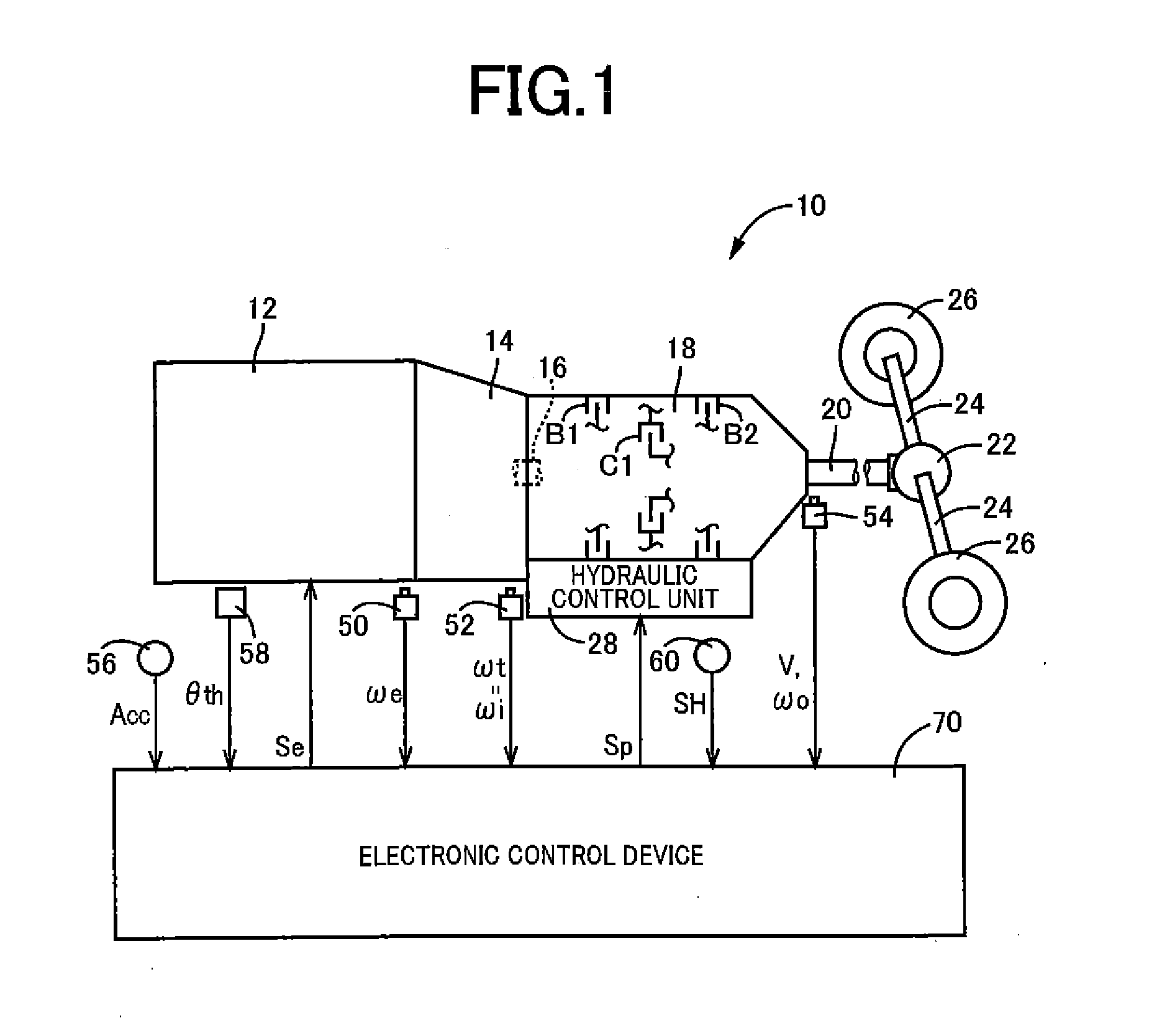
[0024]FIG. 1 is the schematic view for explaining an arrangement of a power transmitting path from an engine 12 to drive wheels 26 of a vehicle 10 to which the present invention is applicable, and a major portion of a control system provided for the vehicle 10. As shown in FIG. 1, a drive force generated by the engine 12 serving as a drive power source is input to an automatic transmission 18 through a torque converter 14 and an input shaft 16, and is transmitted from an output shaft 20 of the automatic transmission 18 to the right and left drive wheels 26 through a differential gear device (differential gear) 22 and a pair of axles (drive shafts) 24 in this order of description.

[0025]The automatic transmission 18 is a known planetary gear type automatic transmission having one planetary gear set or a plurality of planetary gear sets, and a plurality of coupling devices (coupling elements), which are housed in a stationary member in the form of a transmission casing attached to a bo...

second embodiment

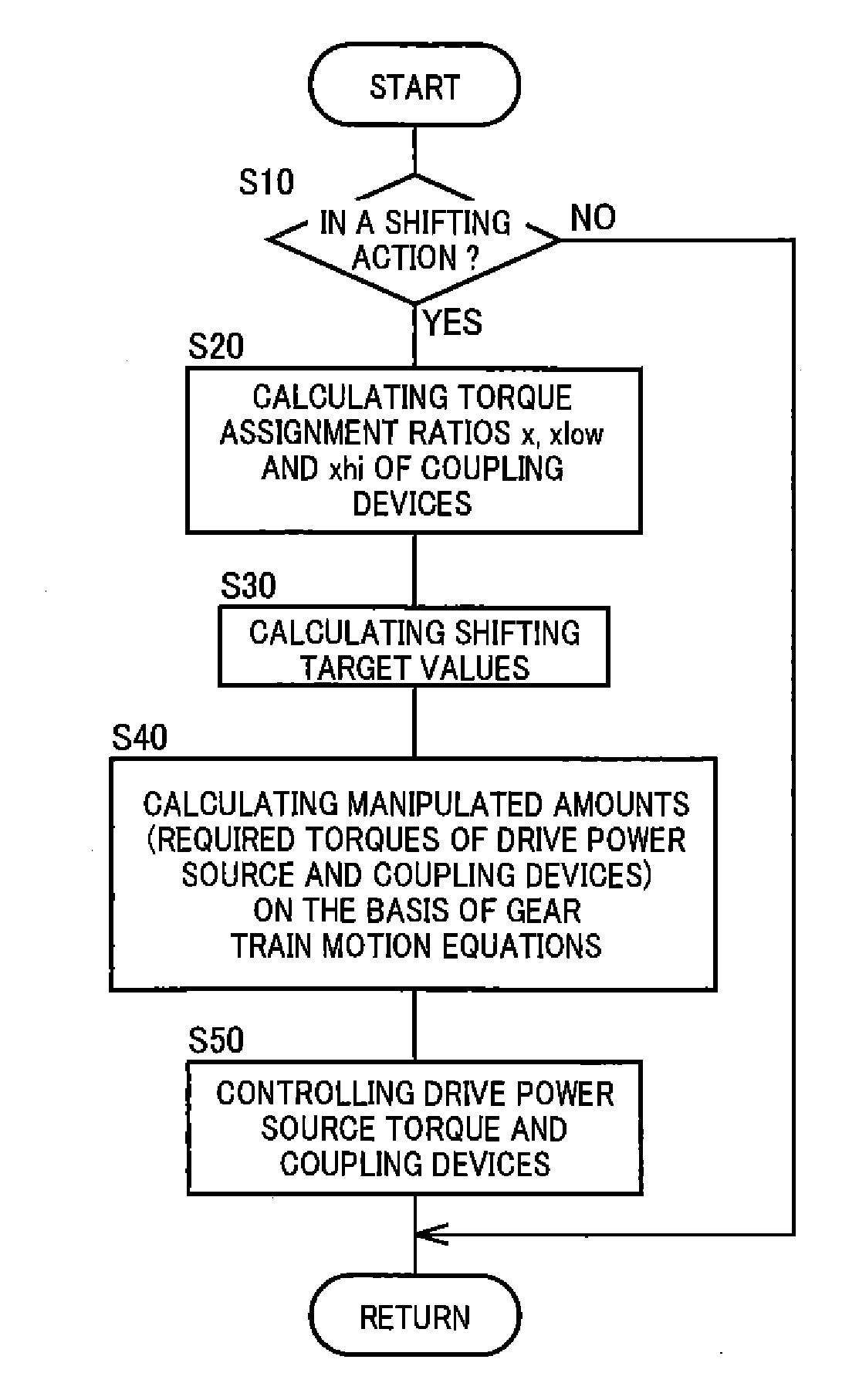
[0049]In the first embodiment described above, the target value of the transmission output torque To in the inertia phase is set as indicated in the time chart of FIG. 4, on the condition that the inertia torque can be entirely offset by the engine torque reduction control. Under some condition depending upon the specific shifting action, the specific two shift positions between which the shifting action takes place, the specific vehicle running speed V during the shifting action, the specific operating state of the engine 12, etc., however, there may be a case where only a part of the inertia torque can be offset. Under such condition, the shifting target value calculating portion 80 according to the present embodiment sets the target value of the transmission output torque To in the inertia phase, on the condition that only a part of the inertia torque can be offset by the engine torque reduction control. That is, the rest of the inertia torque which cannot be offset is added to t...

third embodiment

[0058]The second embodiment described above is configured to set the manipulated amounts so as to intentionally prevent the manipulated amounts from following the shifting target values, for reducing the shifting shock, in order to solve the problem of a risk of increase of the shifting shock due to a delayed change or variation of the actual values of the manipulated amounts controlled so as to follow the target value of the transmission output torque To. Namely, the second embodiment is not configured to set the shifting target values so as to reduce the shifting shock, for controlling the manipulated amounts so as to follow the thus set shifting target values. However, it is basically desirable to set the shifting target values so as to reduce the shifting shock, for controlling the manipulated amounts so as to follow the thus set shifting target values.

[0059]In the preceding second embodiment wherein the torque assignment ratios include the added tie-up amount α, the torque assi...


PUM


Abstract

The present invention executes a desired gear shift of an automatic transmission using gear shift modeling even when there are three control inputs to two target gear shift values. Setting torque share ratio as a constraint on the equation of motion for the automatic transmission is suitable for controlling the transfer of engaging unit torque, which is considered to be difficult in variable speed control, and allows solving of the equation of motion. Viewed from a different angle, because the torque share ratio, which represents the torque transfer, has been set as a constraint, any gear shift pattern can be handled with a single gear shift model.

Description

TECHNICAL FIELD[0001]The present invention relates to a vehicle shift control apparatus configured to implement a shifting control of an automatic transmission, and more particularly to techniques for implementing the shifting control of the automatic transmission according to a shifting model.BACKGROUND ART[0002]There is well known an automatic transmission which has a plurality of coupling devices for transmitting a rotary motion and a torque between an input shaft provided to receive a chive force from a drive power source and an output shaft provided to transmit the drive force to drive wheels, and which is configured to be shifted with concurrently performed engaging and releasing actions of the respective coupling devices. Generally, the automatic transmission of this type is shifted according to manipulated amounts, i.e. control input determined by a control map obtained for each shift position by simulation with an actual vehicle wherein required values (namely, the manipula...

Claims


Application Information

Patent Timeline
Patent Type & Authority Applications(United States)
IPC IPC(8): F16H61/02F16H61/06
CPCF16H61/0213F16H2061/0093F16H61/061B60W30/19F16H61/04F16H63/502F16H59/68F16H59/40F16H59/42
Inventor MASUNAGA, SEIJIHASEGAWA, YOSHIOOTA, KEISUKE
Owner TOYOTA JIDOSHA KK
Why Eureka
Try Eureka