Photoelectric switch for detection of an object and method for operating the same

a technology of photoelectric switch and object, which is applied in the direction of pulse technique, optical radiation measurement, programme control, etc., can solve the problems of easy false operation, degrading the performance of the whole system, and many components and bulky sizes

Active Publication Date: 2015-07-02
NUCTECH CO LTD
View PDF6 Cites 4 Cited by
  • Summary
  • Abstract
  • Description
  • Claims
  • Application Information

AI Technical Summary

Benefits of technology

[0016]controlling and processing, by a control and processing unit, the light signals and / or the electric signal.

Problems solved by technology

This causes numerous components and bulky size.
Furthermore, due to differences in performance among these transmitter tubes, these receiving signals have a bad consistency, which adversely affects performance of the subsequent amplification circuit, thereby degrading performance of the whole system.
However, in practical application, transmissions and receptions of infrared lights are highly negatively affected by environmental lights, such as sunlight and lamplight, and correspondingly false operation is easy to appear when the environment is not good.
In addition, in the design of conventional photoelectric switch, due to fixed intervals among plural transmitter tubes, a resolution for detection is non-adjustable

Method used


Image

  • Photoelectric switch for detection of an object and method for operating the same
  • Photoelectric switch for detection of an object and method for operating the same
  • Photoelectric switch for detection of an object and method for operating the same

Examples


Embodiment Construction

[0024]Exemplary embodiments of the present invention will be described hereinafter in detail with reference to the attached drawings, wherein the like reference numerals refer to the like elements. The present invention may, however, be embodied in many different forms and should not be construed as being limited to the embodiment set forth herein; rather, these embodiments are provided so that the present invention will be thorough and complete, and will fully convey the concept of the disclosure to those skilled in the art.

[0025]In the following detailed description, for purposes of explanation, numerous specific details are set forth in order to provide a thorough understanding of the disclosed embodiments. It will be apparent, however, that one or more embodiments may be practiced without these specific details. In other instances, well-known structures and devices are schematically shown in order to simplify the drawing.

First Overall Architecture

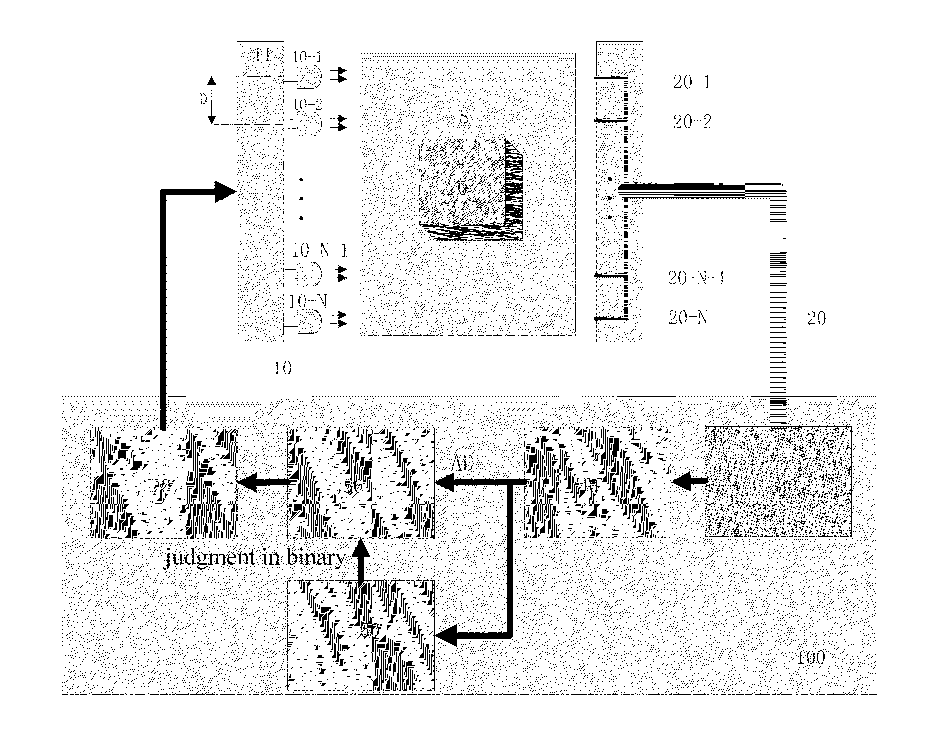
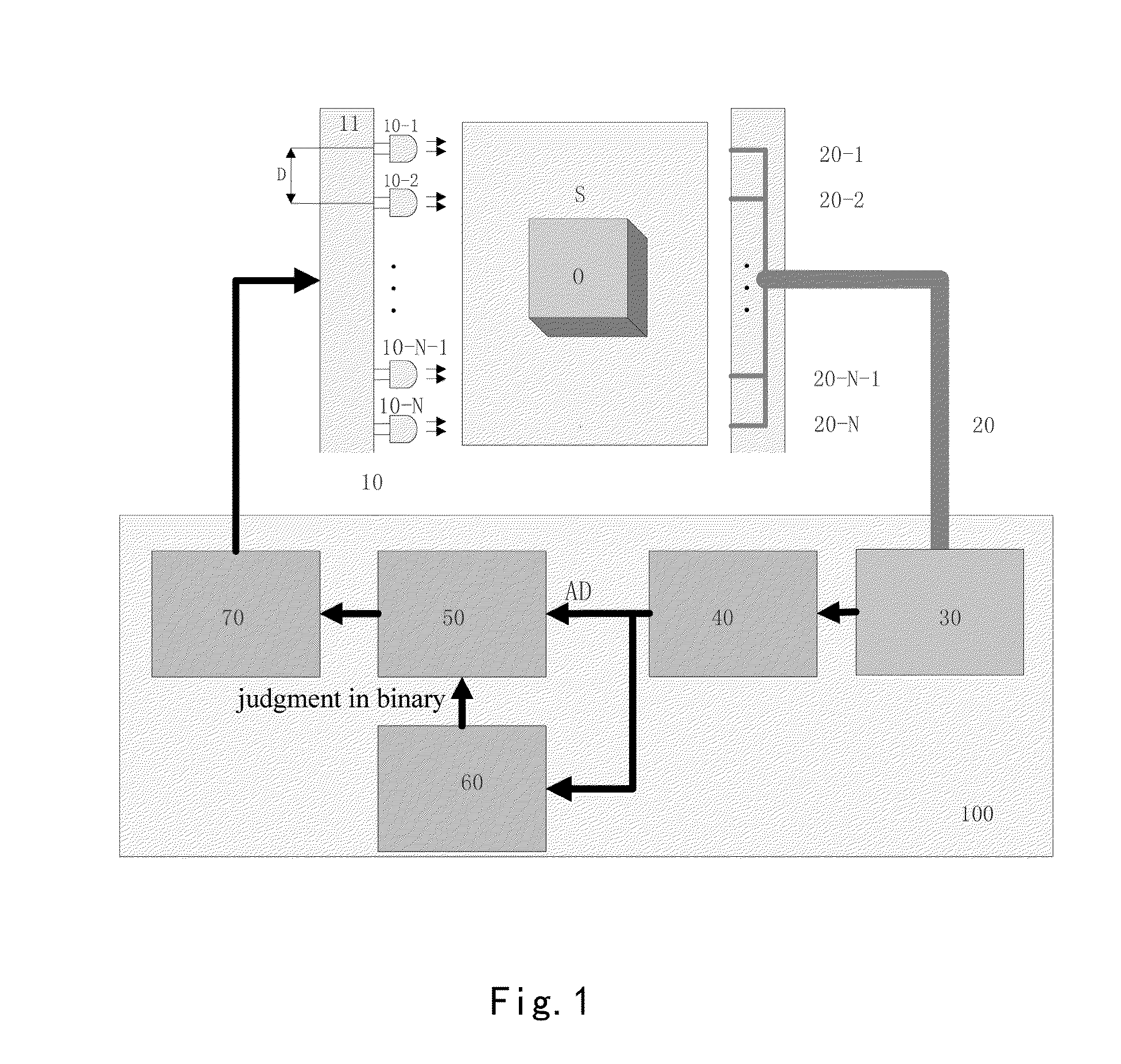
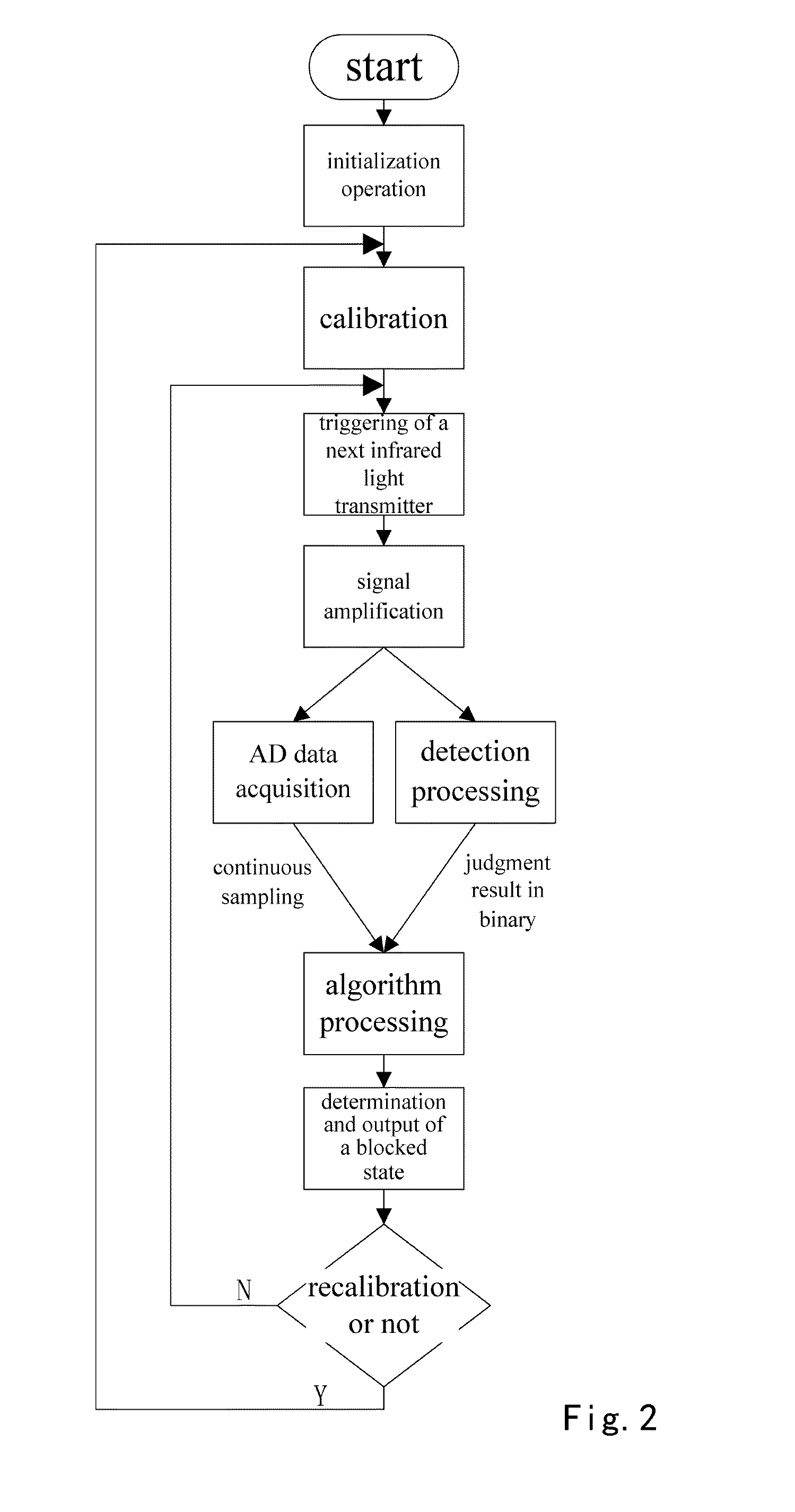
[0026]Referring to FIGS. 1-4 and...


PUM


Abstract

A photoelectric switch for detection of an object. The photoelectric switch comprises: a light transmitter unit comprising plural light transmitters configured to emit plural light signals; a light receiver unit comprising plural optical fiber receivers in one-to-one correspondence with the plural light transmitters and configured to receive the plural light signals and to merge plural light signals, wherein an object detection area is defined between the plural light transmitters and the plural optical fiber receivers; a photoelectric conversion unit connected to the optical fiber receivers and configured to perform photoelectric conversions on the merged light signals outputted by the optical fiber receivers so as to generate an electric signal; and a control and processing unit connected to both the light transmitter unit and the photoelectric conversion unit, and configured to control and process the light signals and/or the electric signal.

Description

CROSS-REFERENCE TO RELATED APPLICATION[0001]This application claims the benefit of Chinese Patent Application No. 201310739805.3 filed on Dec. 26, 2013 in the State Intellectual Property Office of China, the whole disclosure of which is incorporated herein by reference.BACKGROUND OF THE INVENTION[0002]1. Field of the Invention[0003]Embodiments of the present invention relates to security inspection equipment, and in particular to a photoelectric switch for detection of an object, used in security inspection equipment, and a method for operating the photoelectric switch.[0004]2. Description of the Related Art[0005]In conventional security inspection equipment, photoelectric switch for detection of an object is used to judge if an object exists in a detection area or not. Generally, there is one-to-one correspondence between the transmitter tubes and the receiver tubes in conventional photoelectric switch. As a result, more is the transmitter tubes, more is the receiver tubes. This ca...

Claims


Application Information

Patent Timeline
Patent Type & Authority Applications(United States)
IPC IPC(8): G01V8/24
CPCG01V8/24G05B19/042G05B2219/26F16P3/144H03K17/943H03K2217/94026H03K2217/94112
Inventor ZHANG, JINYULIAO, LEIDING, HUITANG, HUZHANG, LI
Owner NUCTECH CO LTD
Why Eureka
Try Eureka