Method, apparatus, and program for encoding image, method, apparatus, and program for decoding image, and image processing system

a technology for image processing and image quality, applied in the field of image processing system, can solve the problems of not providing a color image quality improvement method, insufficient improvement in image quality, and distortion of encoding,

Active Publication Date: 2015-07-02
SAMSUNG ELECTRONICS CO LTD
View PDF8 Cites 53 Cited by
  • Summary
  • Abstract
  • Description
  • Claims
  • Application Information

AI Technical Summary

Benefits of technology

[0022]The filter information generation unit may determine an optimal value of filter information so that an error...

Problems solved by technology

Compared with an original signal of the 4:4:4 format, not only encoding distortion but also image quality deterioration due to sub-sampling occurs in the color difference signal.
All of the above-mentioned techniques of the related art do not provide a color image quality improvement method for bringing a deteriorated color difference image having a 4:2:0 format after encoding close to a undeteriorated color difference image having a 4:4:4 format before encoding.
For this reason, although the techniques...

Method used


Image

  • Method, apparatus, and program for encoding image, method, apparatus, and program for decoding image, and image processing system
  • Method, apparatus, and program for encoding image, method, apparatus, and program for decoding image, and image processing system
  • Method, apparatus, and program for encoding image, method, apparatus, and program for decoding image, and image processing system

Examples


first embodiment

[0048]Hereinafter, a first embodiment will be described with reference to the accompanying drawings.

[0049]In the current embodiment, filtering is performed on a color difference image by using a joint bilateral filter which is a reference type filter and setting a luminance image and the color difference image as reference images to thereby reduce noise of the color difference image and to improve the sharpness of the color difference image. In the current embodiment, an encoding side may design a filter parameter indicating the size and strength of a filter. In the current embodiment, the encoding side may design a filter type so as to change a reference image for each block. A decoding side performs filtering by using the designed filter parameter and filter type, and thus it is possible to improve image quality of the color difference image and to improve encoding efficiency.

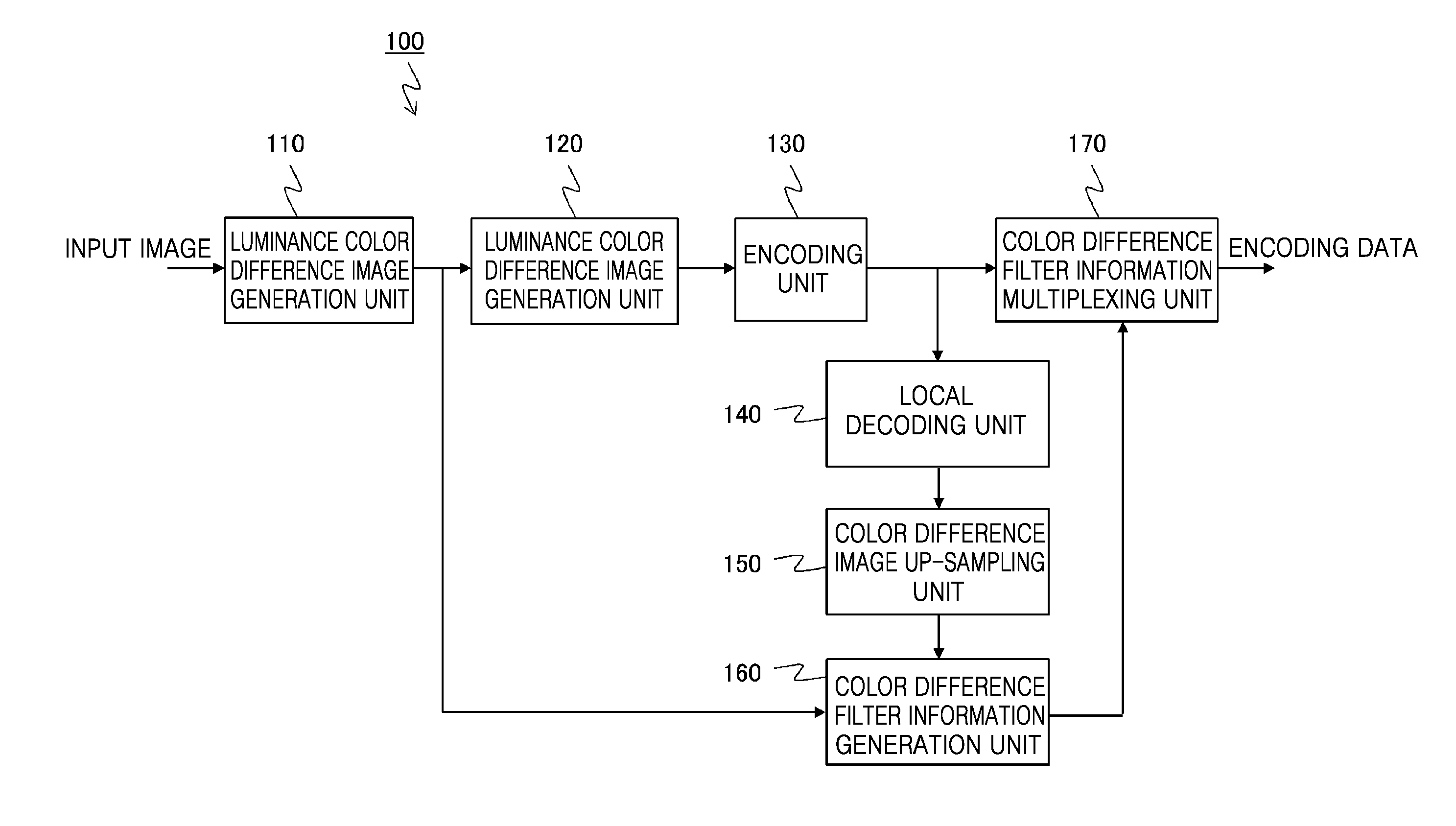
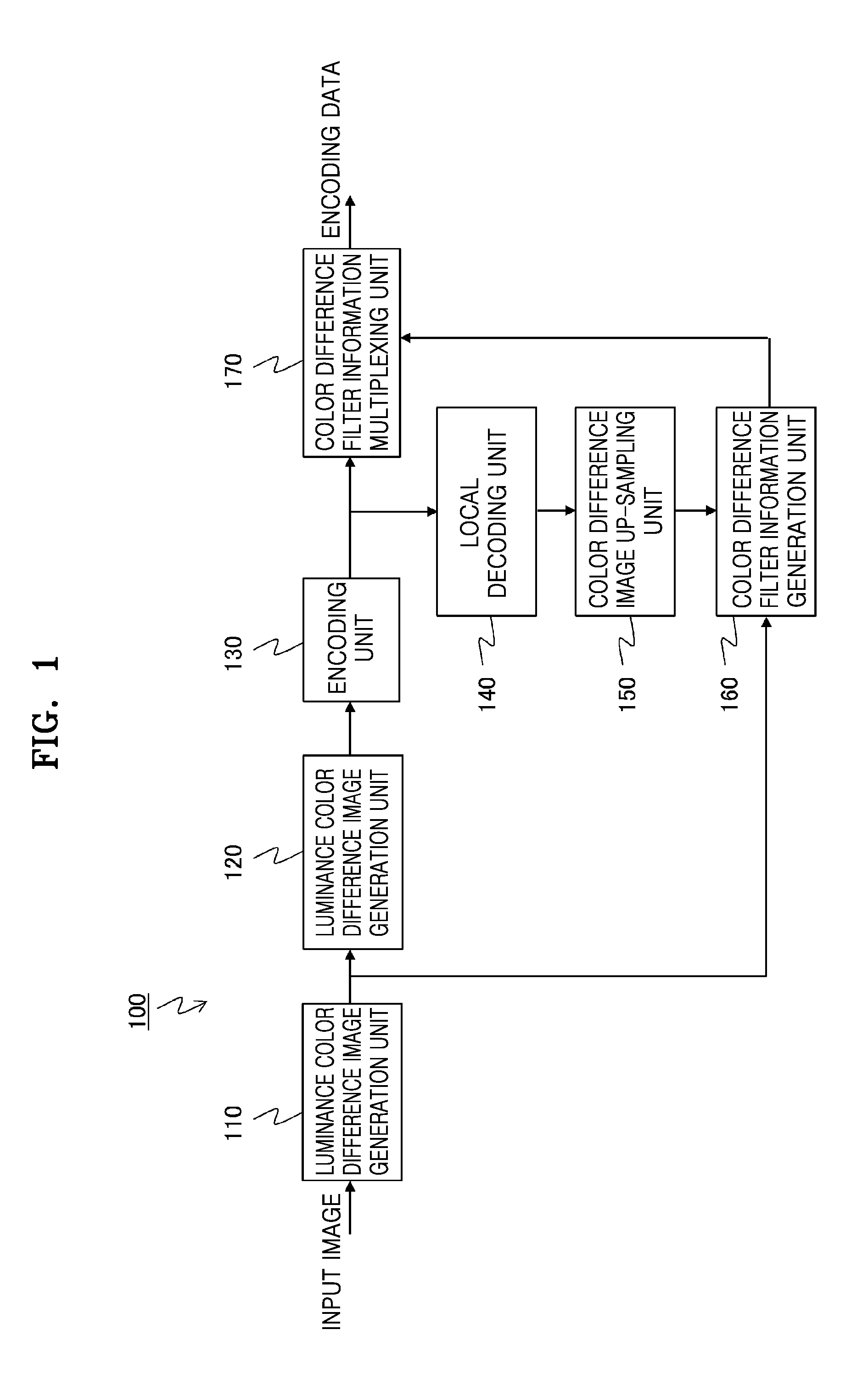
[0050]FIG. 1 is a block diagram illustrating the configuration of an encoding device 100 according to the ...

second embodiment

[0100]Hereinafter, a second embodiment will be described. The current embodiments relates to a method of encoding and decoding an image by performing joint bilateral up-sampling. In addition, a general joint bilateral up-sampling is disclosed in “J. Kopf, M. F. Cohen, D. Lischinski, M. Uyttendaele, “Joint Bilateral Upsampling”, SIGGRAPH2007, No. 96, 2007”.

[0101]FIG. 13 illustrates the configuration of an encoding device 100 according to the current embodiment, and FIG. 14 illustrates the configuration of a decoding device 200 according to the current embodiment. In the current embodiment, the color difference image up-sampling units 150 and 230 described in the first embodiment may not be used by performing joint bilateral up-sampling. In the second embodiment, components other than the color difference image up-sampling units 150 and 230 may be the same as those in the first embodiment.

[0102]Referring to FIG. 14, a local decoding unit 140 of the encoding device 100 may output a gen...

third embodiment

[0106]Hereinafter, a third embodiment will be described. The current embodiment is an example of a method of adding an adaptive parameter of an adaptive bilateral filter to the method described in the first or second embodiment. In addition, a general adaptive bilateral filter is disclosed in “Buyue Zhang, Jan P. Allebach, “Adaptive Bilateral Filter for Sharpness Enhancement and Noise Removal”, IEEE TRANSACTIONS ON IMAGE PROCESSING, VOL. 17, NO. 5, May 2008”.

[0107]The configurations of an encoding device 100 and a decoding device 200 according to the current embodiment are the same as those in the first embodiment (or the second embodiment).

[0108]In the current embodiment, a color difference filtering unit 161 of a color difference filter information generation unit 160 and a color difference filtering unit 240 may perform joint bilateral filtering using an adaptive parameter of an adaptive bilateral filter in operation S102 and operation S103 of FIG. 4. Specifically, the joint bila...


PUM


Abstract

Provided is an image encoding device including an encoding unit that encodes a down-sampling image obtained by performing down-sampling of a color difference signal; a decoding unit that decodes the encoded encoding image; and a filter information generation unit that performs up-sampling of a color difference signal of the decoded decoding image, filters the color difference signal of the decoded image by using the up-sampled color difference signal of the decoded image and a luminance signal as reference signals, and acquires filter information related to the filtering.

Description

RELATED APPLICATIONS[0001]This application claims the benefit of Japanese Patent Application No. 2013-267440, filed on Dec. 25, 2013, in the Japanese Patent Office and Japanese Patent Application No. 2014-211917, filed on Oct. 16, 2014, in the Japanese Patent Office, the disclosures of which are incorporated herein in their entireties by reference.BACKGROUND[0002]1. Field[0003]One or more exemplary embodiments relate to a method, apparatus, and program for encoding an image, a method, apparatus, and program for decoding an image, and an image processing system.[0004]2. Description of the Related Art[0005]Techniques capable of suppressing the deterioration of an image quality while increasing encoding efficiency in applying an image encoding technique such as JPEG, MPEG2, H. 264, or HEVC. For example, when an image deteriorated due to encoding is decoded, noise of the decoded image may be reduced by applying a post filter.[0006]A bilateral filter disclosed in C. Tomasi and R. Manduch...

Claims


Application Information

Patent Timeline
IPC IPC(8): H04N19/85H04N19/136H04N19/44
CPCH04N19/85H04N19/136H04N19/44H04N19/186H04N19/59H04N19/86H04N19/80
Inventor WADA, NAOFUMI
Owner SAMSUNG ELECTRONICS CO LTD
Why Eureka
Try Eureka