
Electode catheter and method for manufacturing the same

a technology of electrodes and catheters, applied in the field of electrode catheters, can solve the problems of poor kink resistance and torque transmissibility of catheter shafts, poor pushability of catheter shafts, and wires extending inside the shafts, etc., and achieves good kink resistance and torque transmissibility, high rigidity, and no excessive change of rigidity

Active Publication Date: 2015-07-09
JAPAN LIFELINE CO LTD
View PDF7 Cites 8 Cited by
  • Summary
  • Abstract
  • Description
  • Claims
  • Application Information

AI Technical Summary

Benefits of technology

The present invention provides an electrode catheter with a small outer diameter that has high rigidity and good kink resistance, torque transmissibility, and pushability in the entire shaft. The catheter shaft is made of a metal tube and a resin tube, which prevents excessive rigidity change between the proximal and distal ends. The method of manufacturing the electrode catheter ensures that the shaft is firmly joined and avoids interference between the lead wire and the wire extending inside the shaft.

Problems solved by technology

However, the catheter shaft having a small outside diameter as described above does not have good kink resistance and torque transmissibility because it has low rigidity.
Further, the catheter shaft having a small outside diameter has a poor pushability.
Moreover, in a catheter shaft having the single lumen structure like the one constituting the electrode catheter described in Patent Document 1, lead wires extending inside the shaft and a wire for pulling operation which moves in an axial direction inside the shaft easily interfere with each other.
Consequently, the lead wires may be damaged or broken.

Method used


Image

  • Electode catheter and method for manufacturing the same
  • Electode catheter and method for manufacturing the same
  • Electode catheter and method for manufacturing the same

Examples


first embodiment

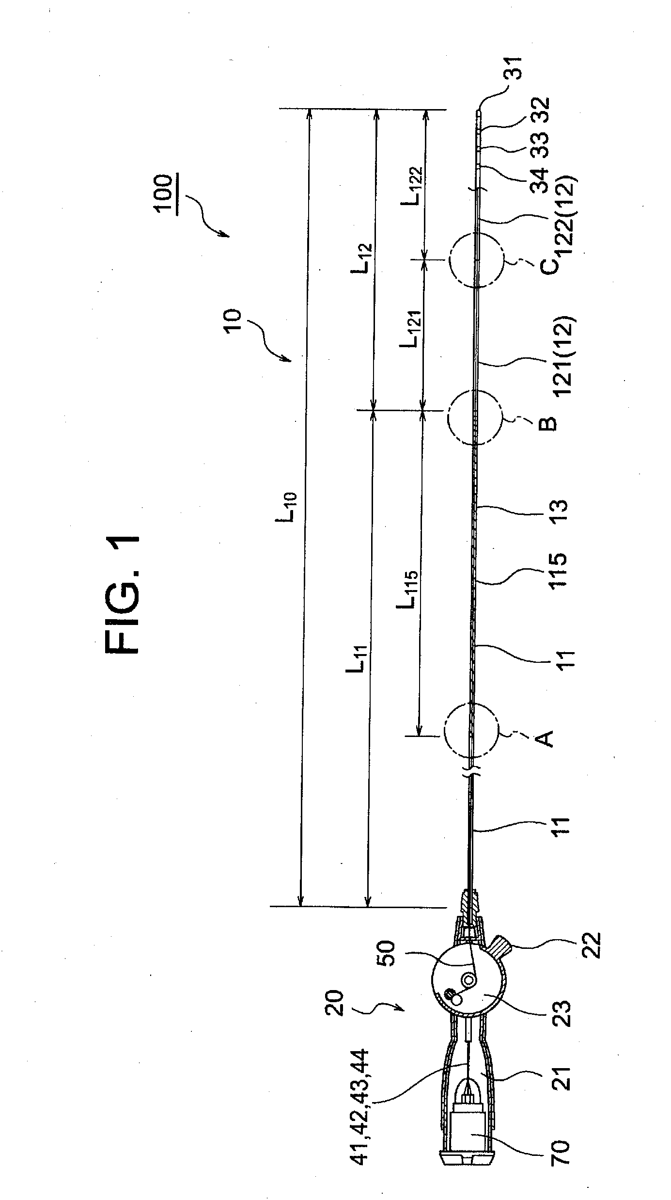
[0072]An electrode catheter 100 of this embodiment illustrated in FIG. 1 to FIG. 7 is, for example, used for measuring potential in a region of a pulmonary vein of heart, or the like.

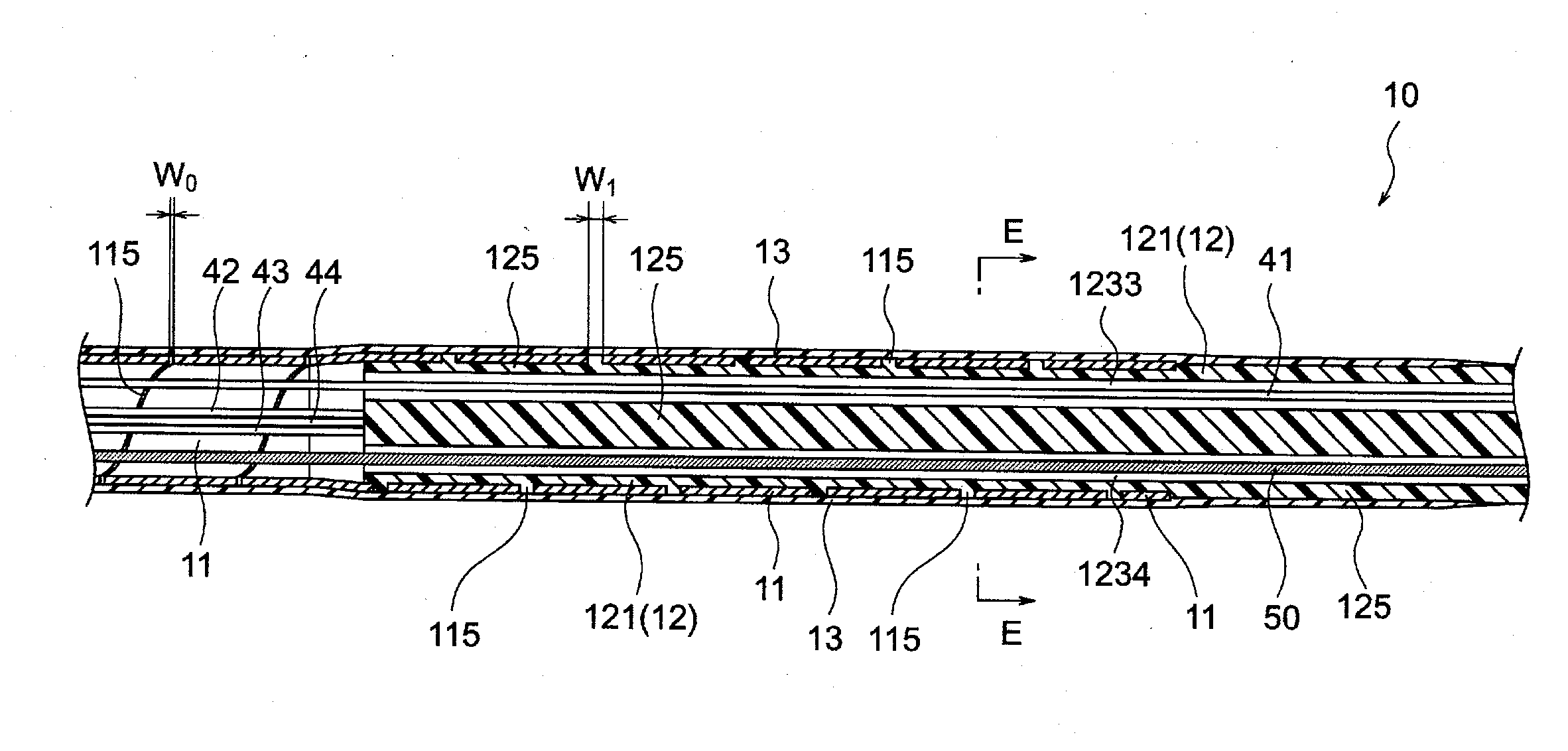
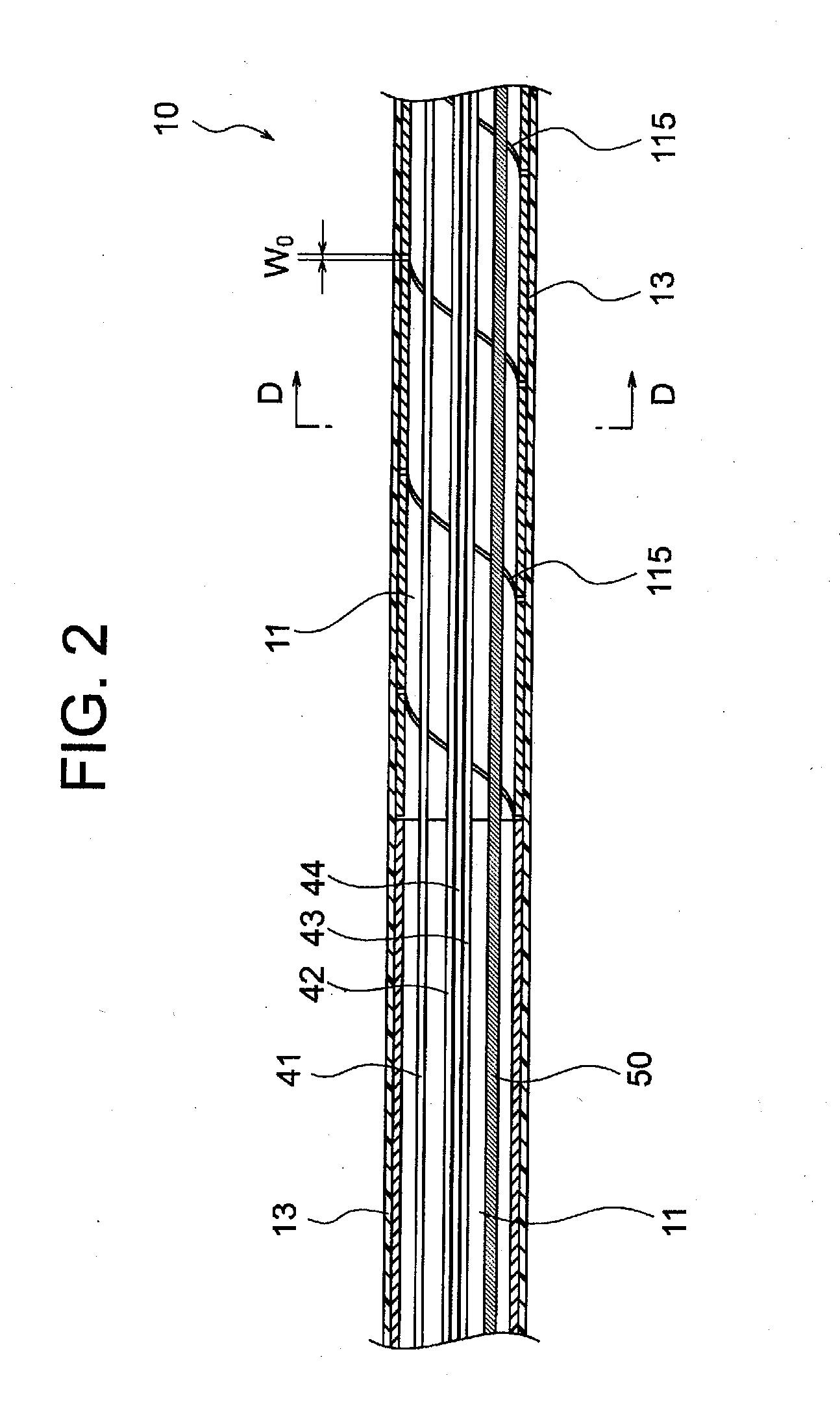
[0073]This electrode catheter 100 includes a catheter shaft 10, an operating handle 20 connected to a base end side of this catheter shaft 10, a connector 70 attached inside this operating handle 20, a tip electrode 31 attached to a tip of the catheter shaft 10, three ring-shaped electrodes 32, 33, 34 attached to an outer periphery of a tip portion of the catheter shaft 10, four lead wires 41, 42, 43, 44 having respective tips connected to the tip electrode 31 and the ring-shaped electrodes 32, 33, 34, respectively, extending along an axial direction inside, the catheter shaft 10, and having respective rear ends connected to the connector 70, and a pull wire 50 having its tip fixed to the tip electrode 31, extending along the axial direction inside the catheter shaft 10, and having a rear end fixed to a...

second embodiment

[0170]An electrode catheter 150 illustrated in FIG. 10 to FIG. 13 is used for measuring potential in a portion of a pulmonary vein of heart, or the like, and has a catheter shaft 15, an operating handle 25 connected to a base end side of this catheter shaft 15, a connector (not illustrated) attached inside this operating handle 25, a tip electrode 31 attached to a tip of the catheter shaft 15, seven ring-shaped electrodes 32, 33, 34, 35, 36, 37, 38 attached to an outer periphery of a tip portion of the catheter shaft 15, eight lead wires 41, 42, 43, 44, 45, 46, 47, 48 having respective tips connected to the tip electrode 31 and the ring-shaped electrodes 32 to 38, respectively, extending along an axial direction inside the catheter shaft 15, and having respective rear ends connected to the connector, and a core wire 55 having its tip fixed to the tip electrode 31, extending along the axial direction inside the catheter shaft 15, and having a rear end fixed to a base end portion of t...


PUM

PropertyMeasurementUnit
diameteraaaaaaaaaa
lengthaaaaaaaaaa
lengthaaaaaaaaaa

Abstract

An electrode catheter is provided with a catheter shaft (10), an operating handle (20) provided with a connector (70), a tip electrode (31), ring-shaped electrodes (32 to 34), lead wires (41 to 44) connected to the tip electrode (31) and the ring-shaped electrodes (32 to 34), respectively, and a pull wire (50) fixed to the tip electrode (31). The catheter shaft (10) is constituted of a shaft proximal end portion (11) formed of a metal tube having a spiral slit (115) formed in a tip portion, a shaft distal end portion (12) formed of a resin tube of multi-lumen structure, and a resin covering layer (13) covering outer peripheries of the shaft proximal end portion (11) and a rear end portion of the shaft distal end portion (12). The lead wires (41 to 44) and the pull wire (50) extend through different lumens of the resin tube constituting the shaft distal end portion (12). This electrode catheter can is exhibit good kink resistance, torque transmissibility and pushability in the entire shaft.

Description

TECHNICAL FIELD[0001]The present invention relates to an electrode catheter provided with a tip electrode.BACKGROUND ART[0002]Electrode catheters are known as medical devices used for diagnosing or treating irregular heartbeats of heart.[0003]As an electrode catheter for measuring potential in a portion such as a pulmonary vein of heart, the present applicant has proposed an electrode catheter having a catheter shaft, an operating handle connected to a base end side of the catheter shaft, a catheter tip part formed in a circular loop shape connected to a tip side of the catheter shaft, plural ring-shaped electrodes attached to an outer periphery of the catheter tip part, and a tip electrode attached to a tip of the catheter tip side (see Patent Document 1).[0004]The catheter shaft (catheter main body) constituting the electrode catheter described in Patent Document 1 has a single lumen structure (thin long tubular structure having one internal hole) having a resin tube (first tube) ...

Claims


Application Information

Patent Timeline
Patent Type & Authority Applications(United States)
IPC IPC(8): A61B5/00B32B38/00B32B37/14
CPCA61B5/6852B32B37/142B32B38/0012B32B2457/00A61B2562/12A61B2562/222B32B2535/00A61B2562/0209A61M25/0012A61M25/0013A61B5/6869A61B5/6876A61N1/056A61B5/283
Inventor MORI, KENJI
Owner JAPAN LIFELINE CO LTD
Learn More