Method for manufacturing multi-fiber bundles

a multi-fiber bundle and fiber bundle technology, applied in the direction of manufacturing tools, soldering devices, instruments, etc., can solve the problem of inability to connect, and achieve the effect of improving the amount of available optical fiber, excellent single-mode fiber, and reducing cos

Inactive Publication Date: 2015-07-09
THE UNITED STATES OF AMERICA AS REPRESENTED BY THE SECRETARY OF THE NAVY
View PDF8 Cites 5 Cited by
  • Summary
  • Abstract
  • Description
  • Claims
  • Application Information

AI Technical Summary

Benefits of technology

[0007]Applicant has determined that the utilization of an MFB in place of a multicore fiber, in accordance to one or more embodiments of the instant invention, has several advantages. First, because a single mode fiber, for example, is used to form the MFB, the amount of available optical fiber is significantly increased. There are numerous fiber manufacturers capable of making excellent single mode fiber and at a reduced cost when compared to a multicore fiber counterpart. Using single mode fiber also enables the capability of bundling fibers with vastly different core parameters and host materials (generally not achievable with multicore fiber). Second, by bundling individual fibers, the connectivity issue becomes nonexistent. Because each fiber end is free, connecting to the MFB is achieved by splicing to the individual fibers. Fusing the fibers or using silica coatings also provides thermal and mechanical robustness to the MFB. Since the host material is same, thermal uniformity across the bundle prevents non-uniform strain transfer. Lastly, the fibers can be modified prior to bundling to facilitate the incorporation of complicated structures within the fiber. This allows the fibers to be individually treated before they are integrated into a MFB. Some examples might include writing FBG arrays into the fibers (e.g., via “strip and re-coat” or in-line with a draw tower) or writing microstructures into the fibers using ultrafast laser processing. Because standard writing and processing techniques are already employed, the added complication of rotational alignment (as with conventional multicore fiber) is not necessary and greatly simplifies the manufacturing of optical devices.

Problems solved by technology

Second, by bundling individual fibers, the connectivity issue becomes nonexistent.

Method used


Image

  • Method for manufacturing multi-fiber bundles
  • Method for manufacturing multi-fiber bundles
  • Method for manufacturing multi-fiber bundles

Examples


Embodiment Construction

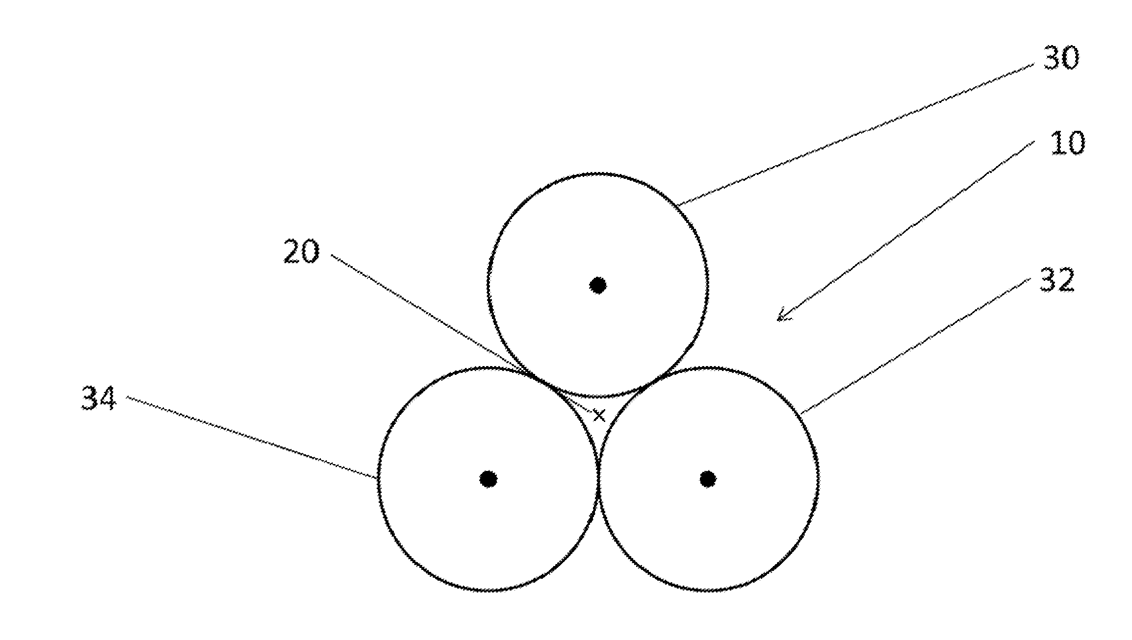
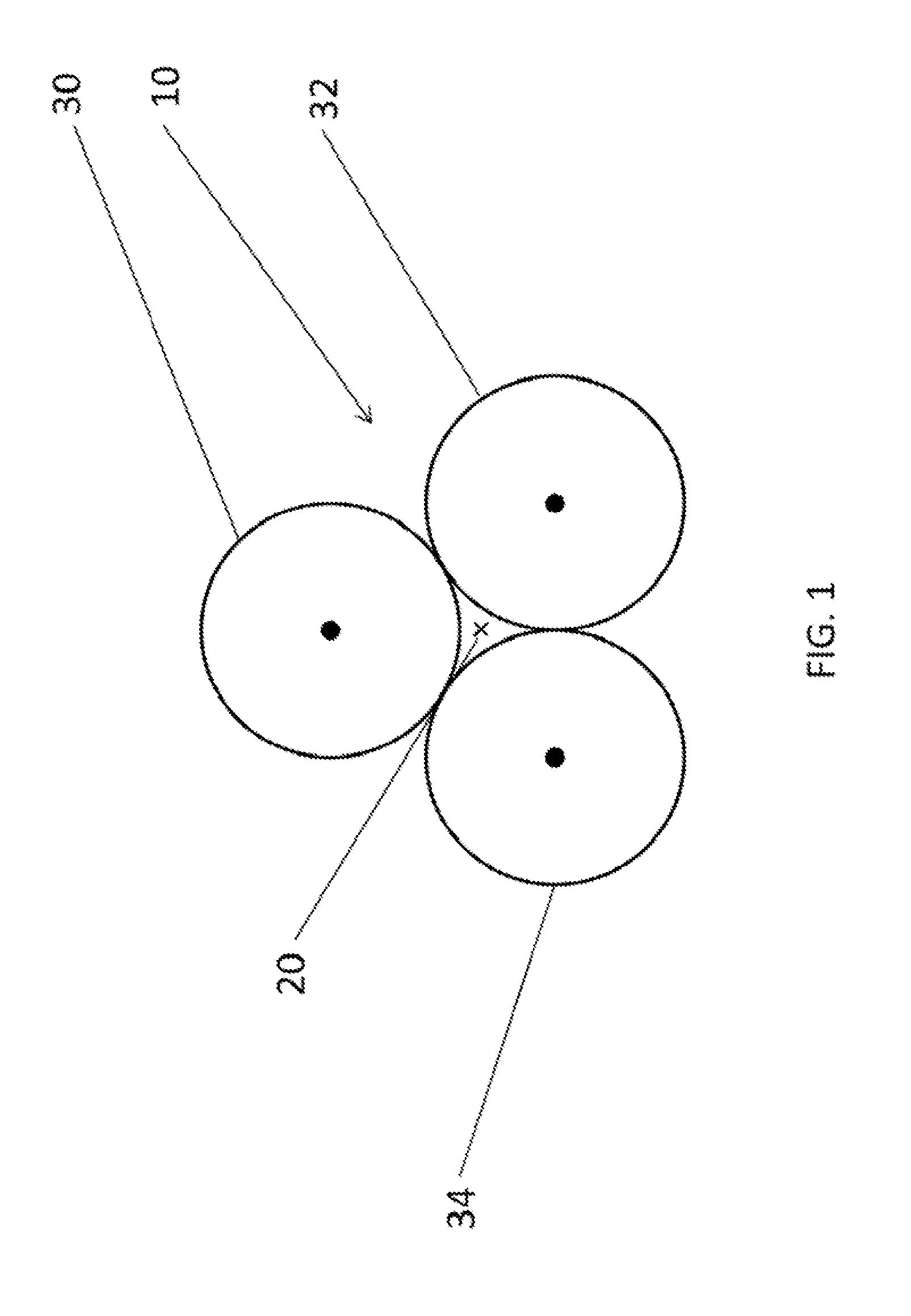
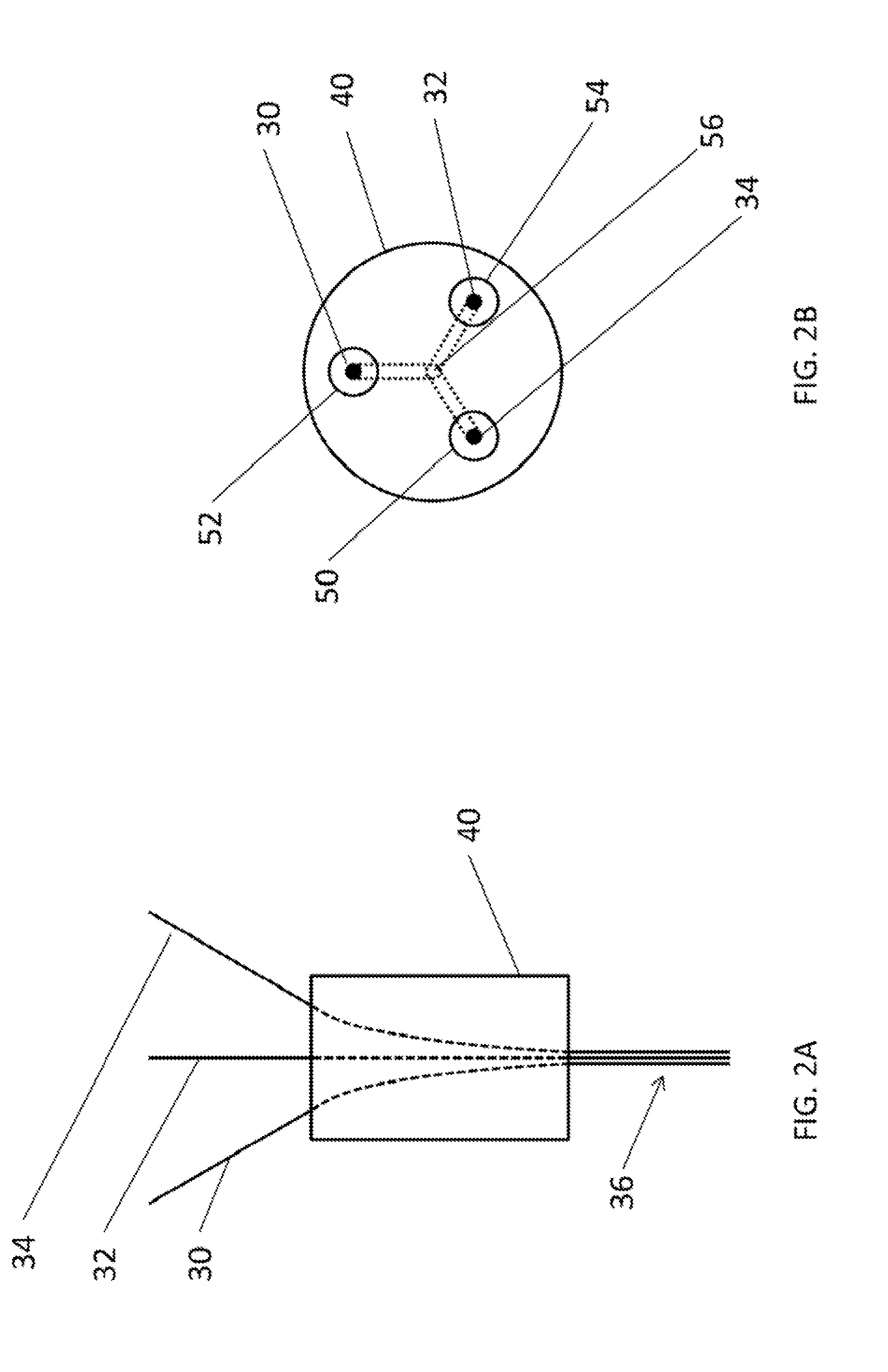
[0037]An embodiment of the invention includes a method of manufacturing a multi-fiber bundle 10, for example, as described by way of illustration in FIGS. 1 and 2A and 2B. The level of zero-bending stress is herein defined at the neutral axis. The multi-fiber bundle 10 includes a multi-fiber bundle neutral axis 20, as shown in FIG. 1. The level of zero-bending stress of the multi-fiber bundle 10 then is herein defined at the multi-fiber neutral axis. The multi-fiber bundle 10 includes at least three standard optical fibers 30, 32, 34. One of ordinary skill in the art will appreciate that although three optical fibers are shown in the figures, more optical fibers may be used in a multi-fiber bundle according to the instant invention depending on the application. The at least three optical fibers 30, 32, 34 includes respective optical fiber neutral axes. The levels of zero-bending stresses of the optical fibers are herein defined at their respective optical fiber neutral axes. The at ...


PUM

PropertyMeasurementUnit
constant distanceaaaaaaaaaa
refractive indexaaaaaaaaaa
bending amplitudeaaaaaaaaaa

Abstract

A method of manufacturing a multi-fiber bundle. The multi-fiber bundle includes a multi-fiber bundle neutral axis. The multi-fiber bundle includes at least three optical fibers. The at least three optical fibers includes respective optical fiber neutral axes. The at least three optical fibers are registered such that at least a portion, of the multi-fiber bundle neutral axis remains at a constant distance front at least a portion of the respective optical fiber neutral axes. The at least three optical fibers are coated with an optical fiber coating material. The at least three coated optical fibers are cured.

Description

CROSS-REFERENCE TO RELATED APPLICATIONS[0001]This application claims priority to U.S. Provisional Patent Application Ser. No. 61 / 924,269, entitled “FABRICATION OF MULTI-FIBER OPTICAL SENSOR / ” to Miller, which was filed on 7 Jan. 2014 and is incorporated herein by reference.BACKGROUND OF THE INVENTION[0002]Multicore optical fiber has many positive attributes, chiefly due to the separation of the cores fern the fiber's neutral axis. This property enables the fiber to be used for differential strain measurements (typically using fiber Bragg gratings) in free space or while attached to a sub-structure. Became cores opposite of the neutral, axis experience tension and compression, the resultant strain vector reveals information about the bending amplitude and orientation.[0003]Despite the potential advantages of multicore fiber, there are numerous drawbacks to using this type of fiber for optical devices. The first drawback is this fiber's availability. Few manufacturers produce molts co...

Claims


Application Information

Patent Timeline
Patent Type & Authority Applications(United States)
IPC IPC(8): G02B6/255C03C25/62B23K1/14G02B1/10B23K1/00C03C25/10C03B37/028
CPCG02B6/2551C03C25/104C03C25/6233B23K2001/12G02B1/10B23K1/0008B23K1/14C03B37/028G02B6/4434G02B6/02042G02B6/06B23K26/32C03C25/14C03C25/16C03C27/08B23K2103/50
Inventor MILLER, GARY A.
Owner THE UNITED STATES OF AMERICA AS REPRESENTED BY THE SECRETARY OF THE NAVY
Why Eureka
Try Eureka