Gas flow indicator

a flow indicator and gas flow technology, applied in instruments, other medical devices, life-saving devices, etc., can solve the problems of increased morbidity and mortality, increased morbidity, and mortality, and the failure of supplemental gas delivery is an acknowledged and feared system risk

Active Publication Date: 2015-07-16
VPAS GRP
View PDF9 Cites 23 Cited by
  • Summary
  • Abstract
  • Description
  • Claims
  • Application Information

AI Technical Summary

Benefits of technology

[0021]Preferably the gas flow indicator apparatus further includes means for preventing component parts of the gas flow indicator apparatus from exiting the gas flow chamber and / or for preventing foreign objects from entering into the gas flow chamber.

Problems solved by technology

Failure to deliver this supplemental oxygen can lead to risk of reduced arterial oxygen tension which, if uncorrected, contributes directly to increased morbidity and mortality.
Failure of supplemental gas delivery is an acknowledged and feared system risk in the hospital environment.
Although most hospital's gas supply systems, from source to supply outlet, are generally monitored, as are complex anaesthetic machines and / or ventilators, the most commonly used, and often most simple, gas delivery devices, systems and / or conduits, are not provided with any gas flow indicator apparatus, or at least any effective or useful gas flow indicator apparatus.
Hence, use of such gas delivery devices, systems, etc., can lead to supplementary gas delivery or supply failure going unnoticed.
This risk is magnified in situations involving gas supply from portable gas tanks or cylinders.
Although putting ones ear at or near a mask, etc., may sometimes identify that gas is flowing, the medical practitioner still has no way of knowing whether the desired flow rate of oxygen (i.e. about 6 L / min) is present in or at the mask.
However, patient's requiring the use of such manual resuscitator devices often have severely compromised respiratory function, which means that they require much higher inspired oxygen concentrations than that of ambient air.
Therefore any loss of supplemental oxygen supply can have catastrophic sequelae if undiagnosed.
Like in the case of the common oxygen mask described above, loss of oxygen supply to a BVM can be, and often is, missed as there is presently no visual flow indicator provided at or proximate the BVM confirming supplemental oxygen inflow.
Again, although the presence of a sound may indicate that gas is flowing, the medical practitioner still has no way of knowing whether the required flow rate of oxygen is present at the BVM.
While some cylinders do have ball-type flow indicators at their supply outlets, such cylinders are often placed in visually obscured positions (e.g. under a patient's bed or transportation trolley), or placed side-ways rendering the ball-type flow indicators inaccurate.
Even more concerning is that newer designs of oxygen cylinders commonly no longer have ball-type or any flow indicator incorporated into their design.
Hence, failure of supplemental gas supply to gas delivery devices or systems is a real and likely problem.

Method used


Image

  • Gas flow indicator
  • Gas flow indicator
  • Gas flow indicator

Examples


Embodiment Construction

[0061]In the following detailed description of the invention, reference is made to the drawings in which like reference numerals refer to like elements throughout, and which are intended to show by way of illustration, specific embodiments in which the invention may be practiced. It is to be understood that other embodiments may be utilised, and that structural changes may be made, without departing from the scope and spirit of the invention.

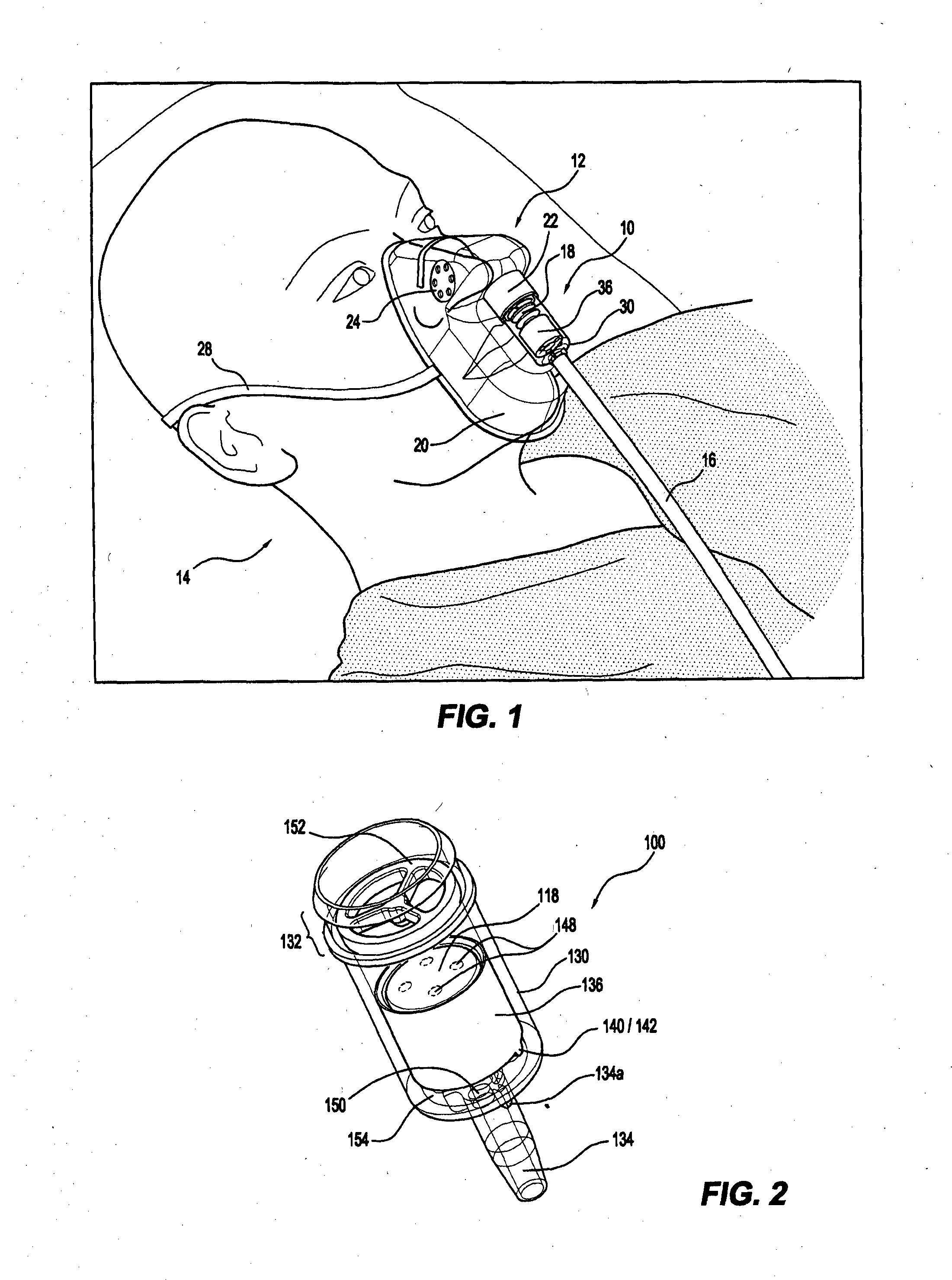
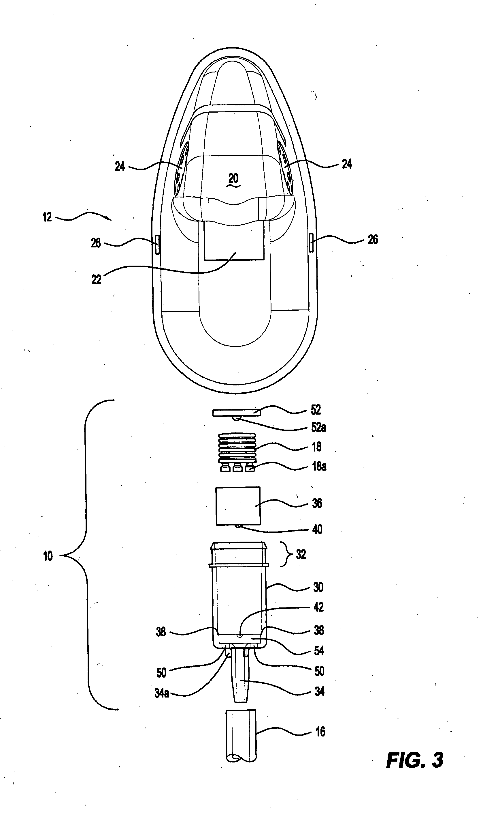
[0062]As will be readily apparent from the detailed description that follows, the present invention relates to gas flow indicator apparatus for gas delivery devices, systems, and / or gas supply conduits, and preferably to gas flow indicator apparatus for medical devices, systems and / or conduits that deliver breathing gas(es) to an individual's airway. The gas flow indicator apparatus of the present invention is particularly well suited to medical gas delivery devices or systems such as, for example, masks, nasal cannulas, or bag valve masks (“BVM...


PUM


Abstract

A gas flow indicator apparatus (10) comprising: a gas flow chamber including at least one transparent portion (30) and at least one opaque portion (36); at least one inlet port (34); at least one outlet port (32); and, at least one gas flow signal means (18) movably disposed within the gas flow chamber. The gas flow indicator apparatus (10) being configured such that when no gas flow is present and/or when a predetermined gas flow rate has not been achieved, the signal means (18) is disposed substantially within one of the transparent portion (30) or the opaque portion (36), and wherein when gas flow is present and/or the predetermined gas flow rate has been achieved, the signal means (18) is moved to be disposed substantially within the other of the transparent portion (30) or the opaque portion (36). Gas delivery devices (12), systems (12) and/or conduits (16) incorporating the gas flow indicator apparatus (10) are also provided in accordance with the invention.

Description

CROSS-REFERENCE[0001]This application claims priority to U.S. Provisional Patent Application Ser. No. 61 / 682,265, filed on Aug. 12, 2012, and U.S. Provisional Patent Application Ser. No. 61 / 763,492, filed on Feb. 12, 2013, the entire contents of each of which are incorporated herein by reference.TECHNICAL FIELD[0002]The present invention relates generally to gas monitoring apparatus. More particularly, the present invention relates to gas flow indicator apparatus for gas delivery devices, systems, and / or gas supply conduits.[0003]It will be convenient to hereinafter describe the invention in relation to gas flow indicator apparatus for medical devices, systems and / or conduits that deliver breathing gas(es) to an individual's airway, however, it should be appreciated that the present invention is not limited to that use only. For example, an alternative use for gas flow indicator apparatus made in accordance with the present invention could include breathing gas delivery devices, sys...

Claims


Application Information

Patent Timeline
Patent Type & Authority Applications(United States)
IPC IPC(8): A61M16/00G01F15/06A61M16/20A61M16/06A61M16/08
CPCA61M16/0003A61M16/06A61M16/08A61M2205/3334G01F15/06A61M2016/003A61M16/20A61M16/0816A61M16/0875A61M2202/0208A61M2205/583A61M16/127
Inventor MATUSIK, MATTHEW
Owner VPAS GRP
Why Eureka
Try Eureka