Combustion system including a piston crown and fuel injector

a combustion system and fuel injector technology, applied in the direction of engines, machines/engines, mechanical equipment, etc., can solve the problems of affecting the emission level of nox and particulate matter, the maintenance and overall cost of the engine system, etc., to reduce the compression ratio of the engine, reduce the emissions, and reduce the effect of engine emissions

Active Publication Date: 2015-07-16
GE GLOBAL SOURCING LLC
View PDF24 Cites 7 Cited by
  • Summary
  • Abstract
  • Description
  • Claims
  • Application Information

AI Technical Summary

Benefits of technology

[0004]In one example, decreasing a compression ratio of the engine may reduce engine emissions. Additionally, providing particular fuel injection parameters (as described herein) may further reduce emissions while maintaining engine performance. Thus, a combustion system operable at a compression ratio from about 13:1 to about 17:1 and including a fuel injector with six to ten apertures configured for reduced emissions (relative to other fuel injectors with different configurations) may result in an engine with reduced NOx and particulate matter emissions over engines with higher compression ratios. In addition to meeting industry defined emissions requirements, reducing particulate matter and NOx emissions may allow for the reduction in size or elimination of an aftertreatment system of the engine. Reducing the size of the aftertreatment system may reduce fuel consumption of the engine while also reducing overall and maintenance costs of the engine.

Problems solved by technology

However, aftertreatment systems may add to maintenance and overall costs of the engine system.
Further, as emissions requirements become more stringent, engines may be required to further reduce NOx and particulate matter emissions.
Characteristics of a combustion system of the engine, such as a compression ratio and fuel injection parameters, may also affect NOx and particulate matter emissions levels.

Method used


Image

  • Combustion system including a piston crown and fuel injector
  • Combustion system including a piston crown and fuel injector
  • Combustion system including a piston crown and fuel injector

Examples


Embodiment Construction

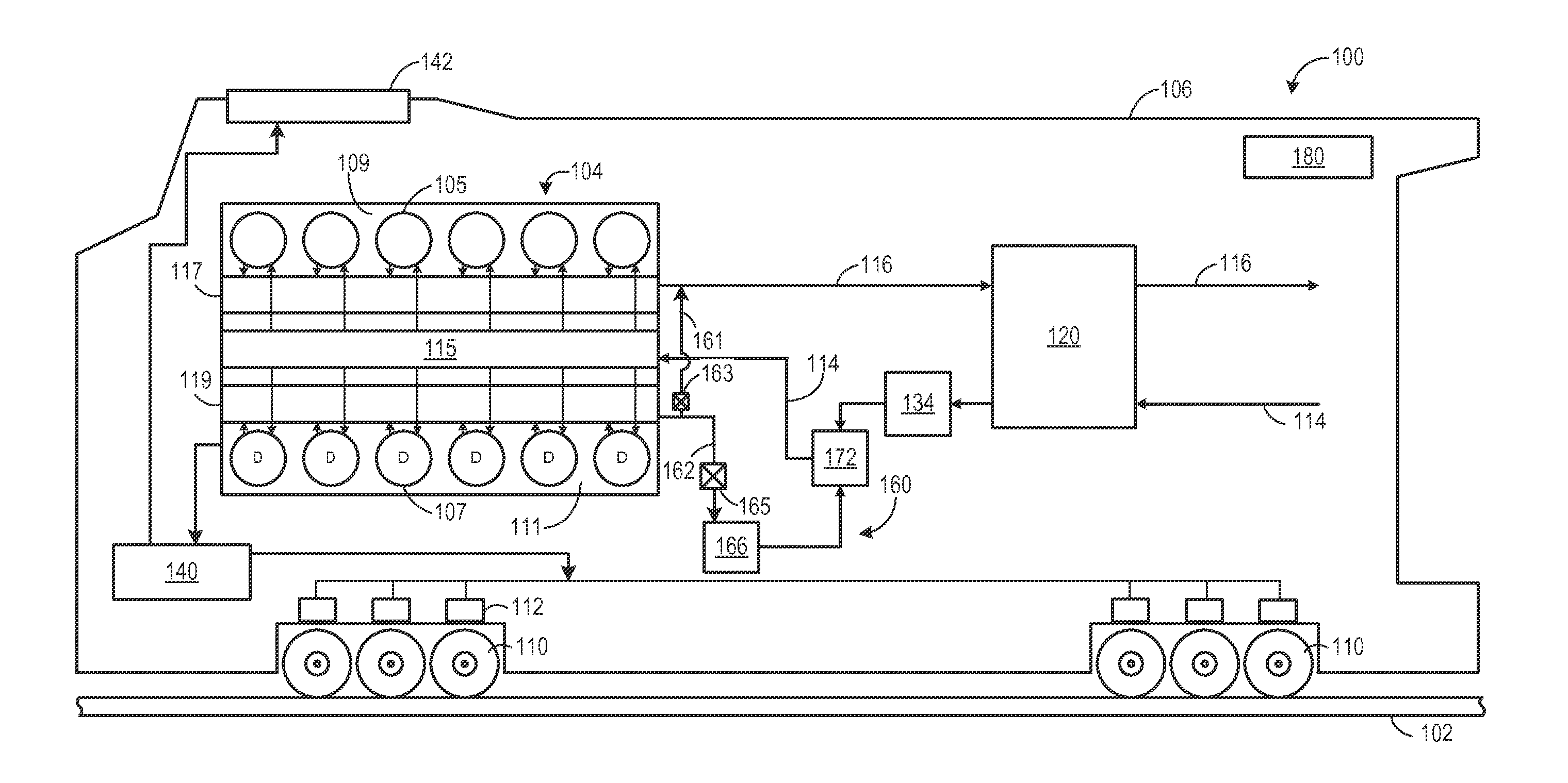
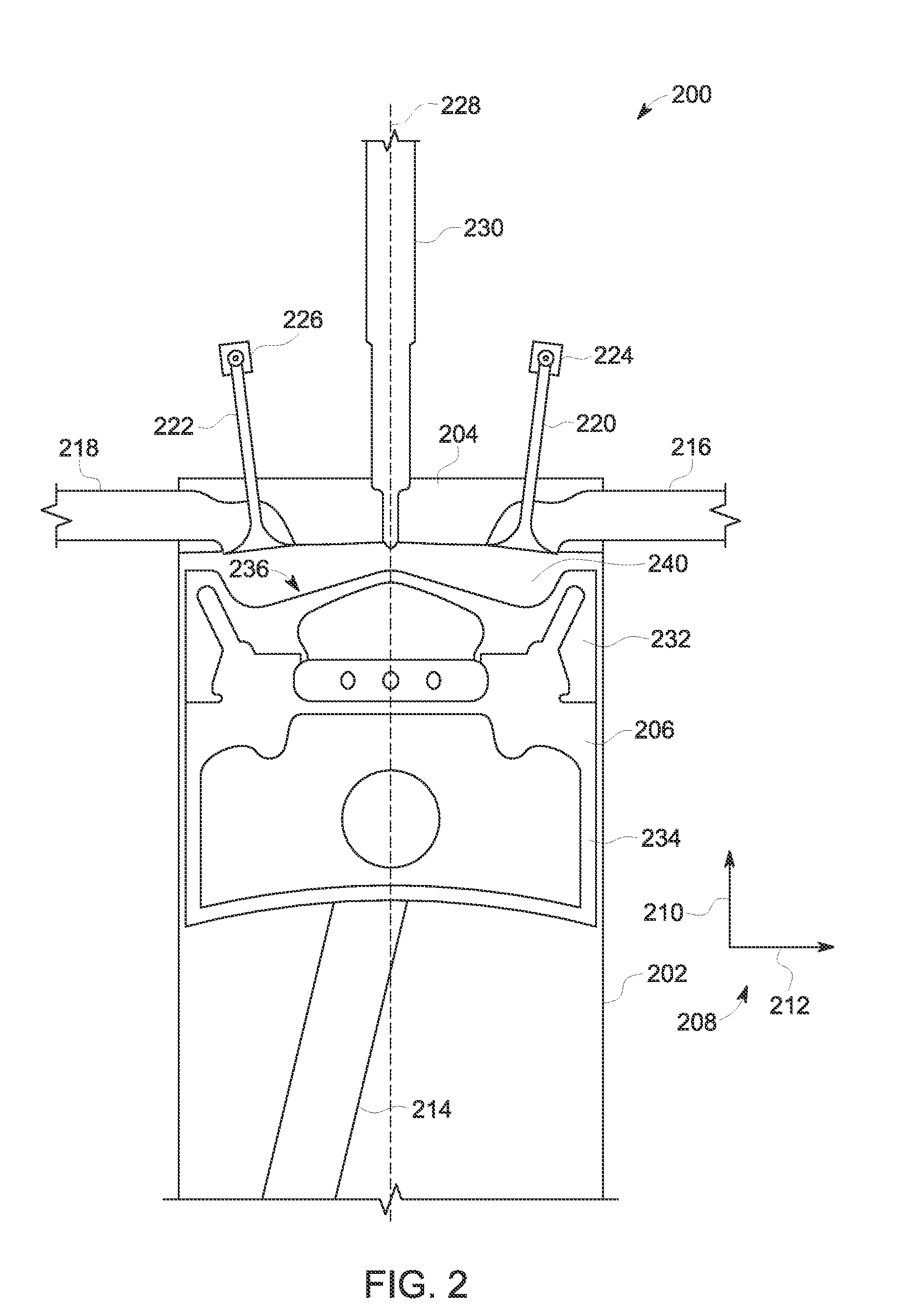
[0014]The following description relates to various embodiments of a combustion system for an engine system, such as the engine system shown in FIG. 1. The combustion system, as shown in FIG. 2, may include a piston crown bowl, a combustion chamber, and a fuel injector. The piston crown bowl may have a geometry forming, at least partially, the combustion chamber. The combustion chamber may be operable at a compression ratio in a range of from about 13:1 to about 17:1. As the compression ratio decreases, NOx and particulate matter emissions may also decrease. As shown in FIG. 3, the piston crown bowl may be sized to provide the desired compression ratio. A geometry of a nozzle of the fuel injector may also affect NOx and particulate matter emissions. Specifically, a number of apertures of the nozzle, along with a geometry of the nozzle apertures, may determine a nozzle flow rate and spray angle which affect NOx and particulate matter emissions from the engine. Thus, the geometry of th...


PUM


Abstract

Various methods and systems are provided for a combustion system of an engine. In one example, a combustion system comprises a piston crown bowl with a central apex, a combustion chamber operable at a compression ratio in a range of from about 13:1 to about 17:1, the combustion chamber formed at least partially by the piston crown bowl, and a fuel injector with a nozzle extending into a central portion of the combustion chamber that is operable to inject fuel directly into the combustion chamber, the nozzle defining a number of apertures that is in a range of from six to ten.

Description

FIELD[0001]Embodiments of the subject matter disclosed herein relate to an engine, engine components, and an engine system, for example.BACKGROUND[0002]Engines may utilize an exhaust aftertreatment system to reduce regulated emissions. However, aftertreatment systems may add to maintenance and overall costs of the engine system. Further, as emissions requirements become more stringent, engines may be required to further reduce NOx and particulate matter emissions. Characteristics of a combustion system of the engine, such as a compression ratio and fuel injection parameters, may also affect NOx and particulate matter emissions levels.BRIEF DESCRIPTION[0003]In one embodiment, a combustion system (e.g., for an engine) comprises a piston crown bowl with a central apex, and a combustion chamber operable at a compression ratio in a range of from about 13:1 to about 17:1. The combustion chamber is formed at least partially by the piston crown bowl. The system further comprises a fuel inje...

Claims


Application Information

Patent Timeline
Patent Type & Authority Applications(United States)
IPC IPC(8): F01N3/10
CPCF01N3/10F02M61/184F02M61/1806F02B23/0645F02M61/1846F02B23/0669
Inventor RECORD, BARRYPRIMUS, ROY JAMESGUMMADAVELLI, VENUYAGER, JAMES HENRYAKINYEMI, OMOWOLEOLA CHUKWUEMEKAKLINGBEIL, ADAM EDGARLAVERTU, THOMAS MICHAEL
Owner GE GLOBAL SOURCING LLC
Why Eureka
Try Eureka