
Virtual image display module and optical lens group

Inactive Publication Date: 2015-07-16
CORETRONIC
View PDF2 Cites 7 Cited by
  • Summary
  • Abstract
  • Description
  • Claims
  • Application Information

AI Technical Summary

Benefits of technology

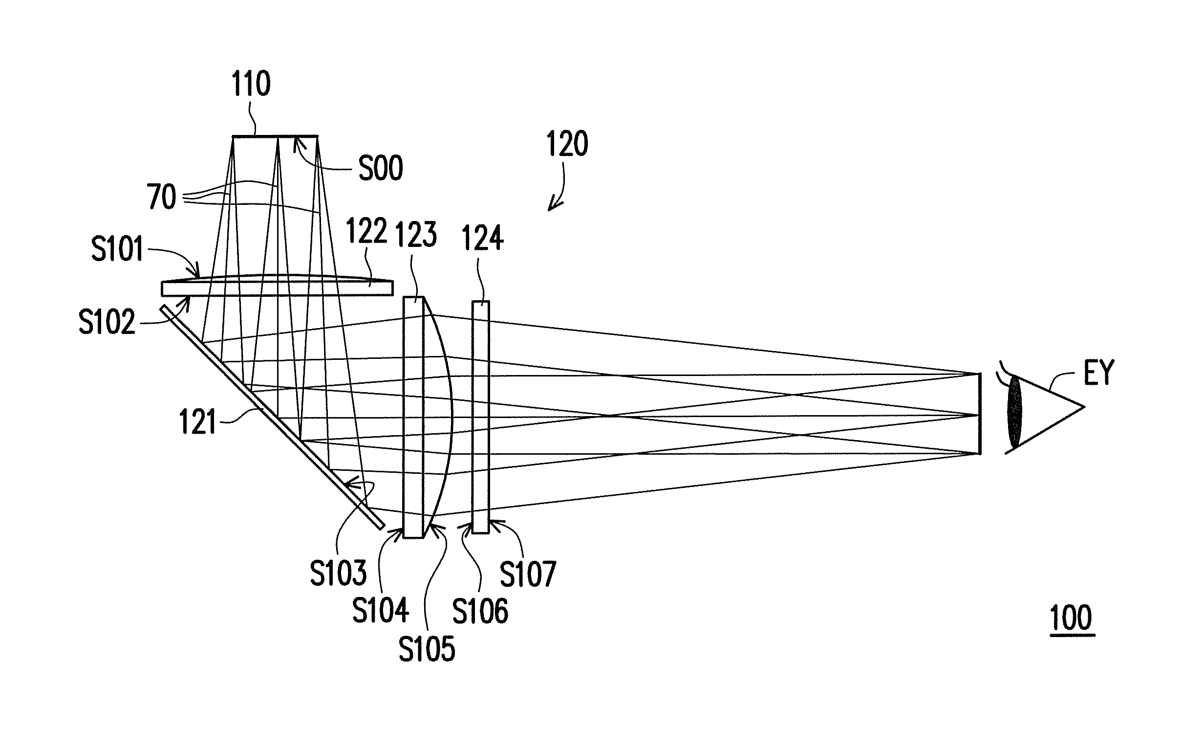
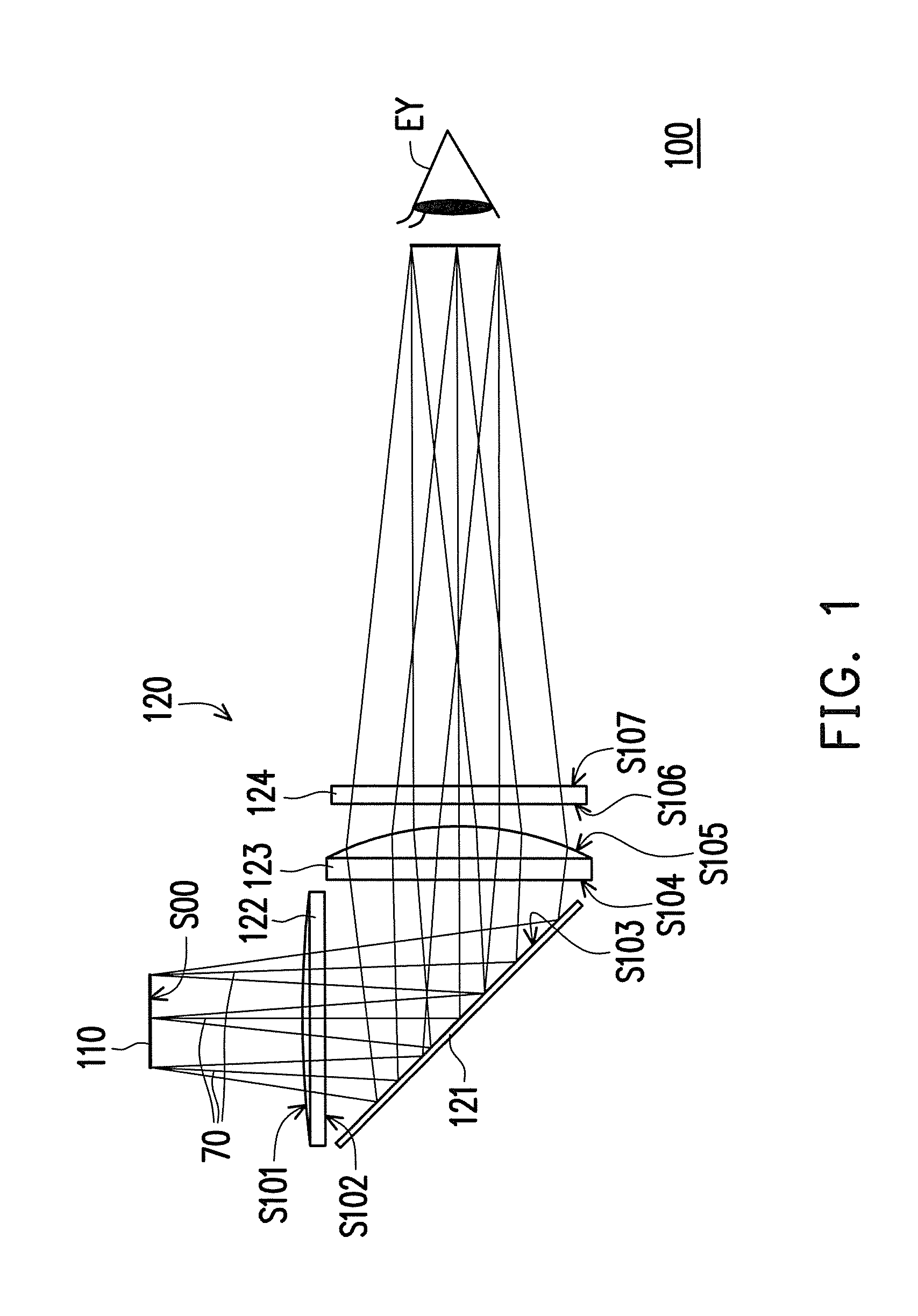
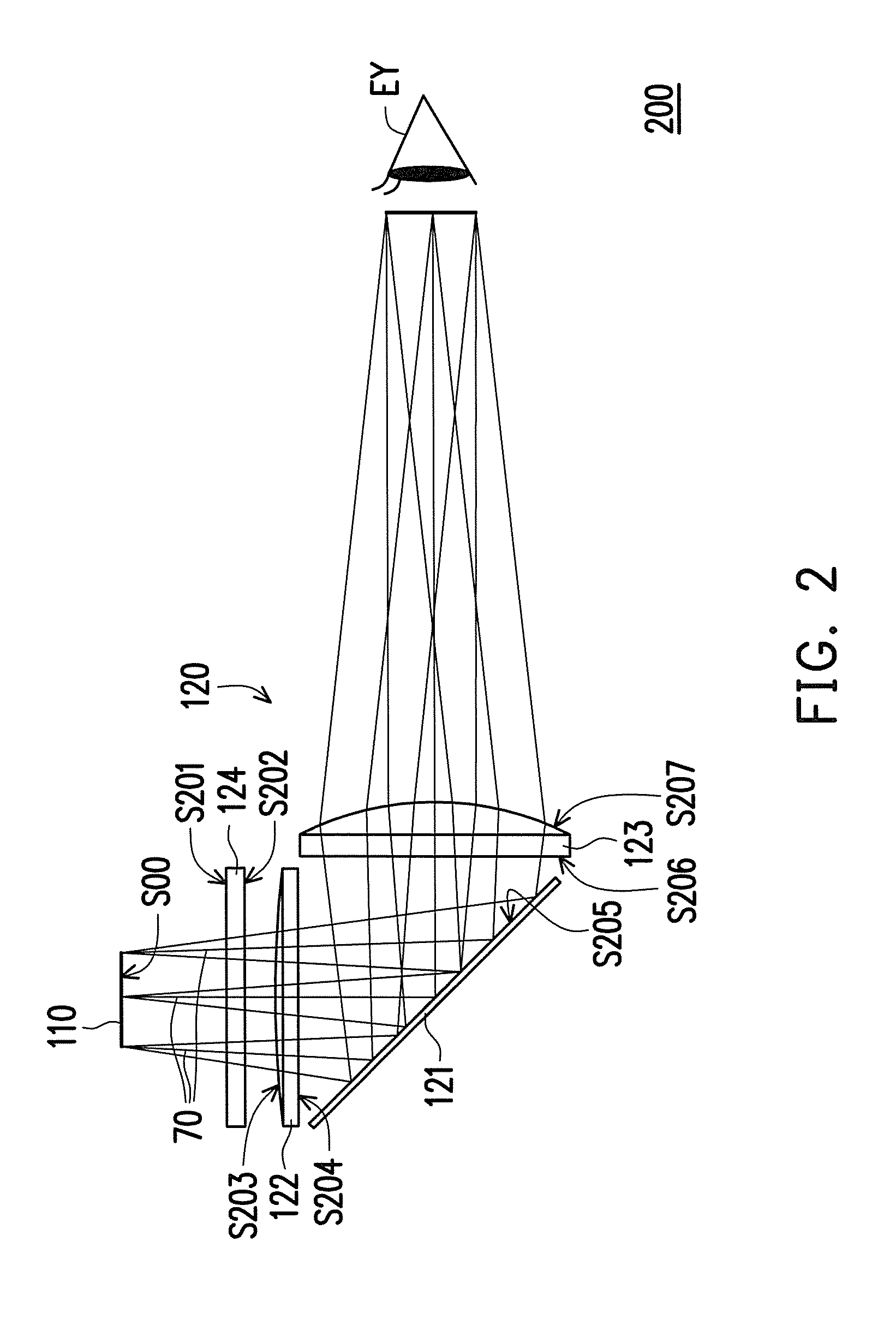
The invention provides a virtual image display module and an optical lens group that have small size, excellent imaging quality and low cost. By using a diffractive optical element, the invention can generate superior imaging quality while keeping the structure lightweight and compact. The diffractive optical element, reflecting unit, lenses and other optical elements can be separate structures, which further reduces the weight of the virtual image display module and optical lens group, and increases product fabrication yield while lowering manufacturing cost.

Problems solved by technology

However, through such configuration, the volume and the weight are easily to cause discomfort for the users.

Method used


Image

  • Virtual image display module and optical lens group
  • Virtual image display module and optical lens group
  • Virtual image display module and optical lens group

Examples


Embodiment Construction

[0028]In the following detailed description of the preferred embodiments, reference is made to the accompanying drawings which form a part hereof, and in which is shown by way of illustration specific embodiments in which the invention may be practiced. In this regard, directional terminology, such as “top,”“bottom,”“front,”“back,” etc., is used with reference to the orientation of the Figure(s) being described. The components of the present invention can be positioned in a number of different orientations. As such, the directional terminology is used for purposes of illustration and is in no way limiting. On the other hand, the drawings are only schematic and the sizes of components may be exaggerated for clarity. It is to be understood that other embodiments may be utilized and structural changes may be made without departing from the scope of the present invention. Also, it is to be understood that the phraseology and terminology used herein is for the purpose of description and ...


PUM


Abstract

A virtual image display module, disposed in front of at least one eye of a user, including an image displaying unit and an optical lens group is provided. The image displaying unit provides an image beam. The optical lens group includes a reflecting unit, a first lens, a second lens and a diffractive optical element, which are disposed on the transmission path of the image beam. The first lens is disposed between the image displaying unit and the reflecting unit. The reflecting unit is disposed between the first lens and the second lens. The second lens is disposed between the reflecting unit and the eye. The diffractive optical element, the reflecting unit, the first lens and the second lens are independent optical elements, respectively. The image beam is transmitted to the eye through the first lens, the reflecting unit, the second lens and the diffractive optical element.

Description

CROSS-REFERENCE TO RELATED APPLICATION[0001]This application claims the priority benefit of Taiwan application serial no. 103101622, filed on Jan. 16, 2014. The entirety of the above-mentioned patent application is hereby incorporated by reference herein and made a part of this specification.BACKGROUND OF THE INVENTION[0002]1. Field of the Invention[0003]The invention generally relates to a display module and an optical module, and more particularly to a virtual image display module and an optical lens group.[0004]2. Description of Related Art[0005]Along with the development of display technology and people's desire for high technology, techniques such as virtual reality and augmented reality have gradually become mature, and head mounted displays (HMDs) are kind of displays implementing the above techniques. The developing history of the HMDs can be traced back to U.S. military in the 1970s, which utilizes an optical projecting system to project the images or text messages of a dis...

Claims


Application Information

Patent Timeline
IPC IPC(8): G02B27/01G02B17/08G02B27/42
CPCG02B27/0172G02B17/0896G02B27/4205G02B2027/0152G02B2027/015
Inventor WEI, CHUNG-TINGHSIEH, CHI-TANGHUANG, TZU-HUA
Owner CORETRONIC
Features
  • Generate Ideas
  • Intellectual Property
  • Life Sciences
  • Materials
  • Tech Scout
  • Unparalleled Data Quality
  • Higher Quality Content
  • 60% Fewer Hallucinations
Learn More