
D-Q Control System and Method for Controlling a Switched Reluctance Motor

a technology of reluctance motor and control system, which is applied in the direction of electric generator control, dynamo-electric converter control, dynamo-electric gear control, etc., can solve the problems of limiting the use of srms, control complexity, ripple, acoustic noise,

Active Publication Date: 2015-07-16
THE UNIVERSITY OF AKRON
View PDF5 Cites 10 Cited by
  • Summary
  • Abstract
  • Description
  • Claims
  • Application Information

AI Technical Summary

Benefits of technology

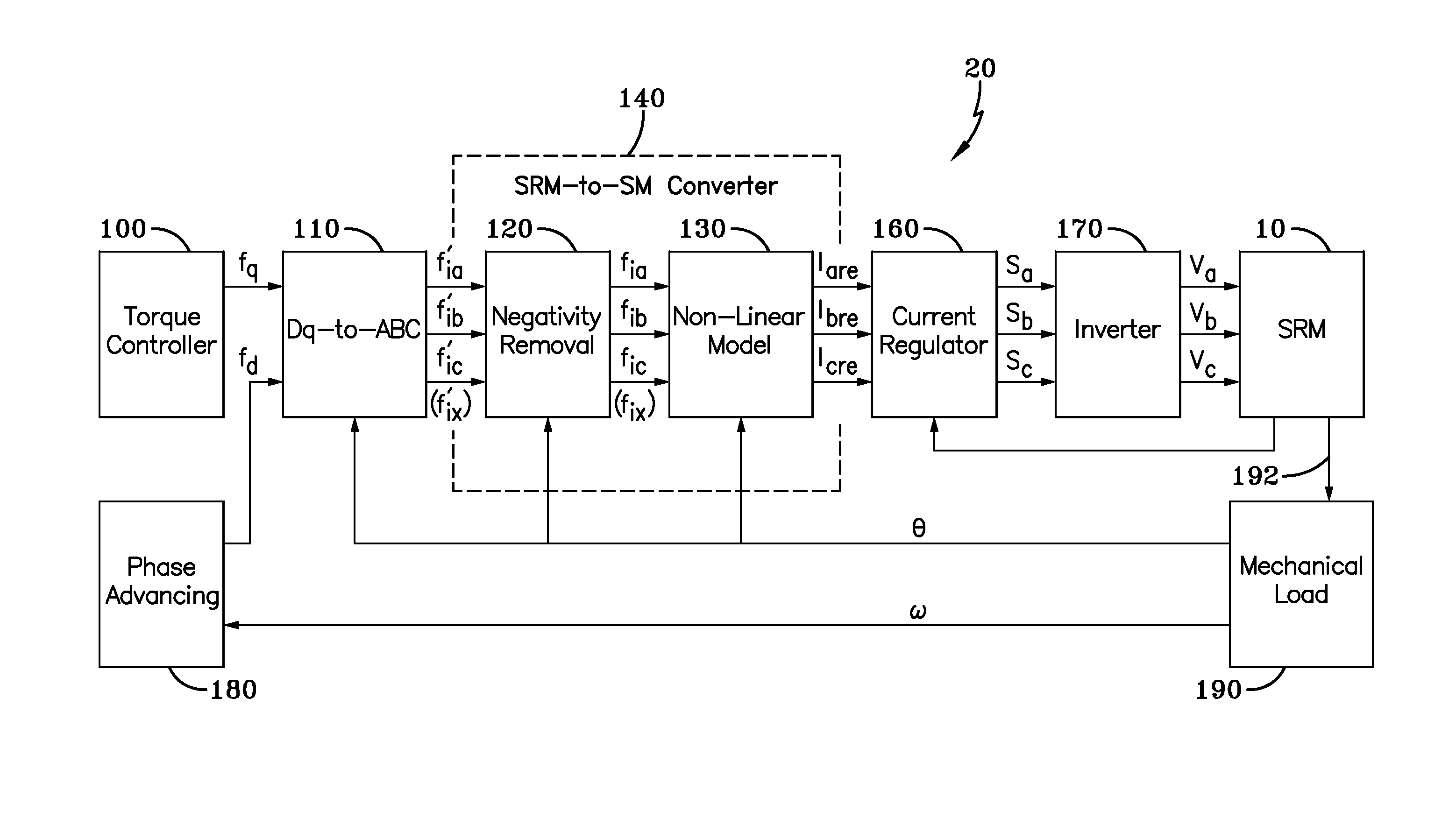
The present invention provides a control system for a switched reluctance motor (SRM) that uses a D-Q or rotating reference frame. The system includes a converter module that converts a torque command signal in the D-Q domain into a sinusoidal torque command signal in an ABC domain, where the signal components together express the torque command as a distorted sinusoid. The converter module also includes a negativity removal module that removes a torque portion of the signal component with a negative value and a non-linear module that modifies the signal components to remove the distortion. The modified signal components are applied to the SRM to control the torque output therefrom. The technical effects include improved performance of the SRM and more accurate control of the motor's torque output.

Problems solved by technology

However, many factors limit the use of SRMs, including their control complexity, torque ripple, acoustic noise, and the need for the SRM to adapt to operating parameter variations.
This is because the phases of the SRM are uncoupled, and the electrical currents used by the SRM are unidirectional.

Method used


Image

  • D-Q Control System and Method for Controlling a Switched Reluctance Motor
  • D-Q Control System and Method for Controlling a Switched Reluctance Motor
  • D-Q Control System and Method for Controlling a Switched Reluctance Motor

Examples


Embodiment Construction

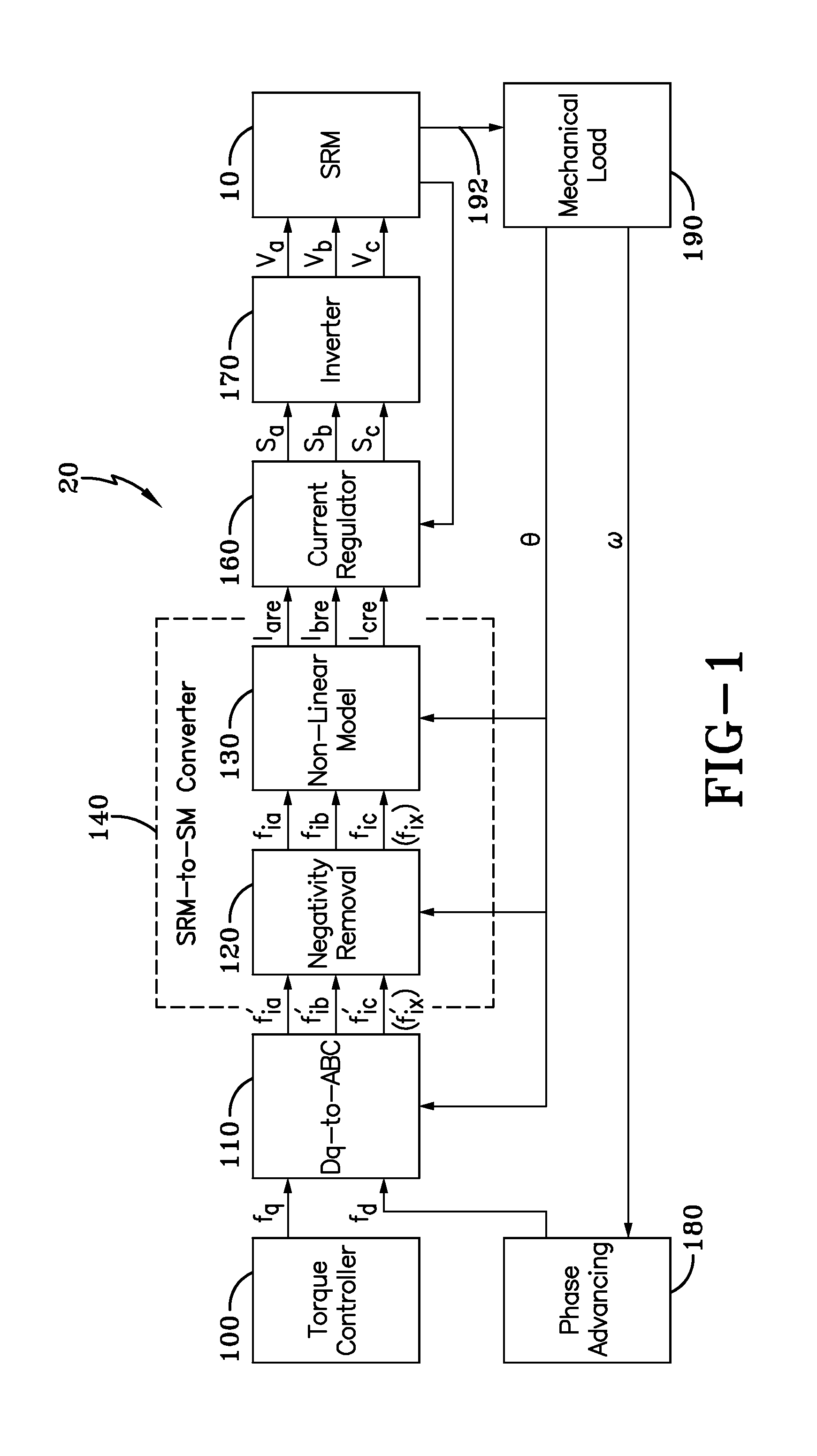
[0014]A D-Q or rotating reference frame control system for controlling a switched reluctance motor (SRM) 10 is generally referred to by numeral 20, as shown in FIG. 1 of the drawings.

[0015]The D-Q control system 20 includes a torque controller 100 that is coupled to a D-Q-to-ABC converter 110. It should be appreciated that for the purposes of the following discussion, the term “D-Q” refers to a rotating reference frame, and as such the D-Q controller 20 is a controller that utilizes a rotating reference frame to carry out the various functions to be discussed. The D-Q-to-ABC converter 110 operates to convert or transform the torque (T) related signal (fq) in the rotating D-Q reference frame (i.e. d-q axes) into a stationary reference frame or phase coordinate system (A,B,C) (i.e. inverse park transformation). As such, the D-Q-to-ABC converter 110 transforms the DC (direct current) quantities of D and Q (i.e. D-Q domain) into three-phase AC (alternating current) quantities A, B, and ...


PUM


Abstract

A D-Q or rotating reference frame control system for a switched reluctance motor (SRM) provides a negativity removal module and a non-linear model module. As such, the control system utilizes control inputs fq and fd, which are converted into the ABC domain as electrical current functions f′ix with negative values. The negativity removal module is configured to share the torque portion of the negative values of the electrical current functions f′ix for each of the three phases of the SRM motor to remove the negative values. The non-linear module corrects the non-linearity of the SRM to smooth the torque that is output. The control system also utilizes a phase advancing module, which outputs fd for achieving a wide range of operating speeds.

Description

CROSS-REFERENCE TO RELATED APPLICATION[0001]This application claims the benefit of U.S. Provisional Application No. 61 / 927,253 filed on Jan. 14, 2014, the content of which is incorporated herein by reference.TECHNICAL FIELD[0002]Generally, the present invention relates to switched reluctance motors (SRM). Particularly, the present invention relates to control systems for SRMs. More particularly, the present invention relates to a control system that controls an SRM using a D-Q rotating reference frame.BACKGROUND OF THE INVENTION[0003]Switched reluctance motors (SRM) provide a low-cost, reliable, high-torque alternative to rare earth-based permanent magnet motors. These qualities of SRMs make them desirable for many industrial, traction and household applications. However, many factors limit the use of SRMs, including their control complexity, torque ripple, acoustic noise, and the need for the SRM to adapt to operating parameter variations.[0004]D-Q or rotating reference frame contr...

Claims


Application Information

Patent Timeline
Patent Type & Authority Applications(United States)
IPC IPC(8): H02P25/08H02P21/00
CPCH02P21/0035H02P25/085H02P21/00H02P25/089H02P25/08H02P6/182H02K19/103H02P25/083
Inventor SOZER, YILMAZHUSAIN, TAUSIFELRAYYAH, ALI
Owner THE UNIVERSITY OF AKRON
Learn More