
Method for connecting a compressor wheel to a shaft of a supercharging device

a supercharging device and compressor wheel technology, which is applied in the direction of machines/engines, liquid fuel engines, turbines, etc., can solve the problems of cumbersome implementation, inability to fix the compressor wheel on the shaft of the rotor, and change in the hot operation of the exhaust-gas turbocharger

Inactive Publication Date: 2015-07-23
BORGWARNER INC
View PDF19 Cites 1 Cited by
  • Summary
  • Abstract
  • Description
  • Claims
  • Application Information

AI Technical Summary

Benefits of technology

The patent describes a method for connecting a compressor wheel to a shaft of a supercharging device using a cold-welding process. This method prevents translatory and rotary movements of the compressor wheel during operation. It involves providing a compressor wheel with a recess and a shaft with a compressor-side shaft end with an outer diameter that is equal to or greater than the inner diameter of the recess. The contact surfaces of the compressor wheel and shaft end are connected through a cold-welding process at the contact surfaces. The invention is advantageously used in exhaust-gas turbocharger rotors.

Problems solved by technology

Changes in imbalance in hot operation of an exhaust-gas turbocharger are caused primarily by settling phenomena of the compressor wheel.
The problem of the solutions proposed in the prior art can be seen primarily in the fact that they are technically cumbersome to implement and nevertheless, at least in part, do not permit adequate fixing of the compressor wheel on the shaft of the rotor.

Method used


Image

  • Method for connecting a compressor wheel to a shaft of a supercharging device
  • Method for connecting a compressor wheel to a shaft of a supercharging device
  • Method for connecting a compressor wheel to a shaft of a supercharging device

Examples


Embodiment Construction

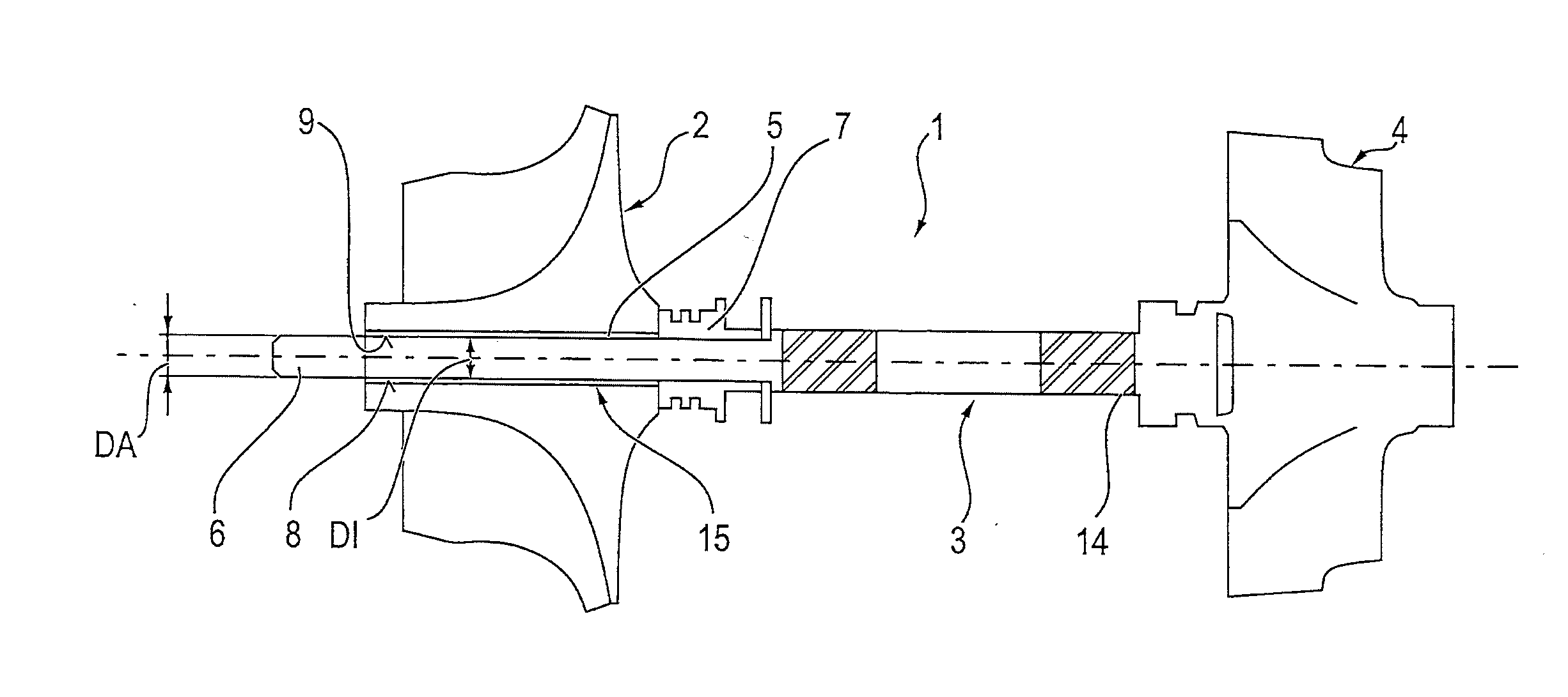
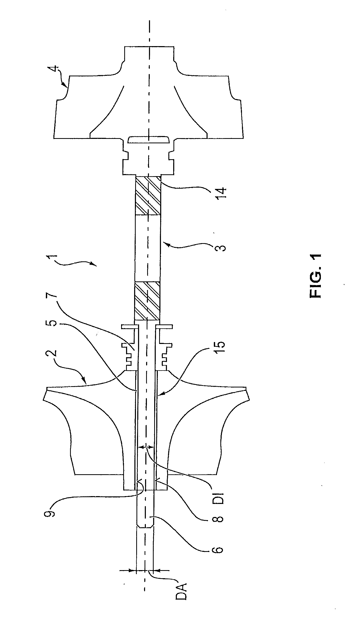
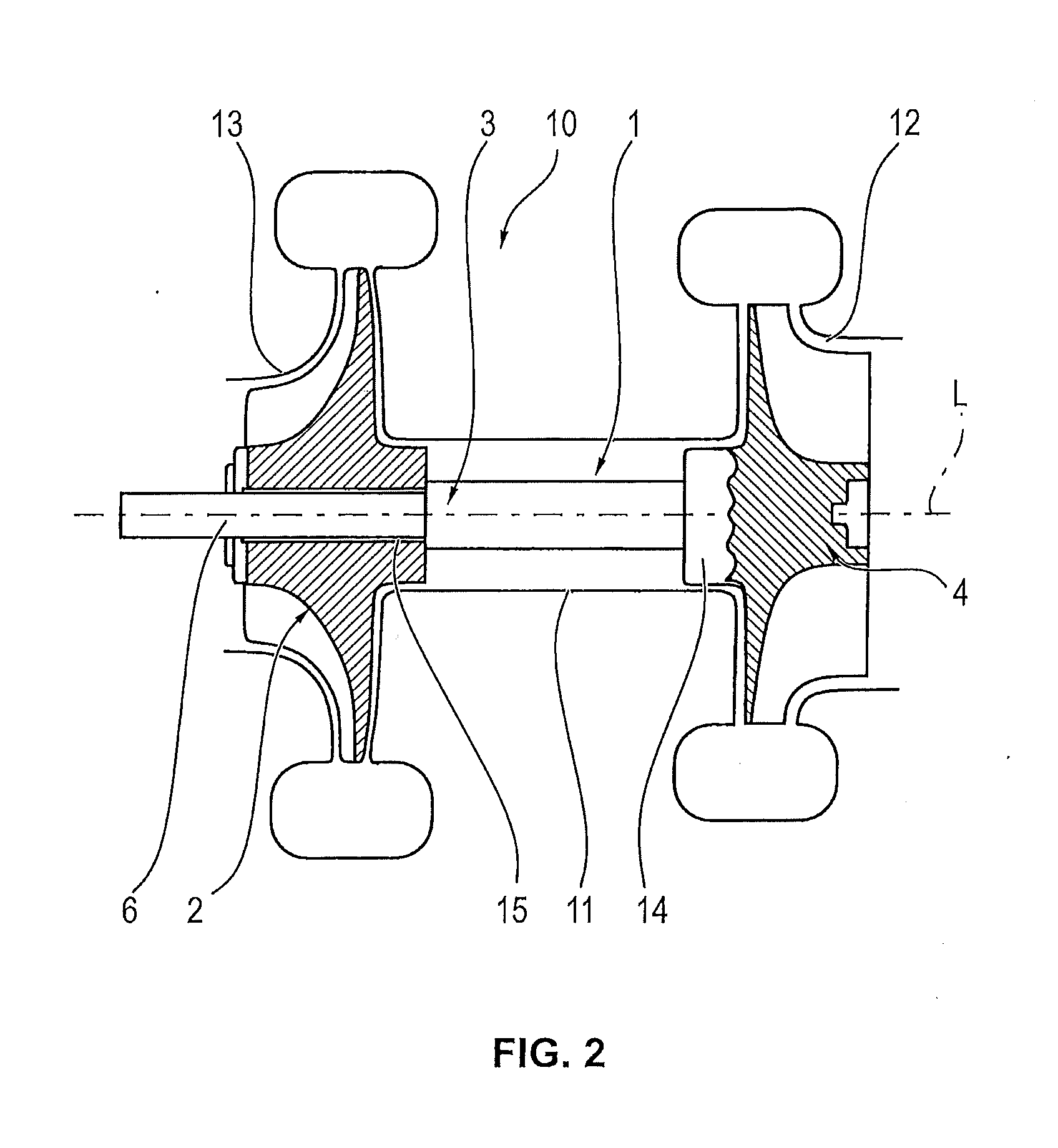
[0020]FIG. 2 illustrates, as an example for a supercharging device according to the invention, an exhaust-gas turbocharger 10 with a rotor 1 which comprises a compressor wheel 2, a shaft 3 and a turbine wheel 4. Here, the compressor wheel 2 is arranged on a compressor-wheel-side shaft end 6, whereas the turbine wheel 4 is arranged on a turbine-wheel-side shaft end 14.

[0021]As has been explained in the introduction, the compressor wheel 2 is fixed to the shaft end 6 via a cold-welding process, as symbolised in FIG. 1 by the double line 15. For this purpose, in the particularly preferred embodiment that is illustrated, the outer diameter DA of the shaft end 6 is configured such that, before the cold-welding process is performed, the outer diameter is larger than the inner diameter DI of the shaft-receiving recess 5 of the compressor wheel 2. The resulting contact surfaces 8 of the shaft end 6 and 9 of the shaft-receiving recess 5 are brought into contact with one another as the compre...


PUM

PropertyMeasurementUnit
outer diameter DAaaaaaaaaaa
outer diameteraaaaaaaaaa
DAaaaaaaaaaa

Abstract

A method for connecting a compressor wheel (2) to a shaft (3) of a supercharging device (1), having the following method steps: providing a compressor wheel (2), having a shaft-receiving recess (5) which has an inner diameter (DI); providing a (3), having a compressor-side shaft end (6) with an outer diameter (DA) which is at least equal to and preferably greater than the inner diameter (DI) of the shaft-receiving recess (5); and connecting the compressor wheel (2) to the compressor-side shaft end (6) by means of a cold-welding process (15) at the contact surfaces (8, 9) thereof.

Description

BACKGROUND OF THE INVENTION[0001]1. Field of the Invention[0002]The invention relates to a method for connecting a compressor wheel to a shaft of a supercharging device at the contact surfaces between compressor wheel and shaft.[0003]2. Description of the Related Art[0004]Changes in imbalance in hot operation of an exhaust-gas turbocharger are caused primarily by settling phenomena of the compressor wheel. Whereas the turbine wheel is permanently connected to the shaft of the rotor via a welding process, the compressor wheel sits more or less loosely on the shaft. In the prior art, interference fits, conical contact surfaces between adjoining components or optimized contact surfaces with increased friction coefficients are proposed for the purposes of reducing the movement of the compressor wheel on the shaft. Examples for this can be found in DE 10 2010 001 965 A1, WO 2010 / 111131 A2, DE 10 2008 053 222 A1 and DE 10 2008 061 167 A1.[0005]The problem of the solutions proposed in the ...

Claims


Application Information

Patent Timeline
Patent Type & Authority Applications(United States)
IPC IPC(8): F04C29/00B23K20/00B23K20/02
CPCF04C29/0078B23K20/002B23K20/02B23K20/023B23K20/1205B23K20/129B23K20/22F04D25/04F04D29/266F01D5/025F05D2230/232B23K2101/001
Inventor ELLENBERGER, DIRK
Owner BORGWARNER INC
Learn More