
Supplying apparatus for supplying combustible material, a gasification apparatus for gasifying combustible material and method for gasifying combustible material

Active Publication Date: 2006-10-31
EBARA CORP
View PDF11 Cites 3 Cited by
  • Summary
  • Abstract
  • Description
  • Claims
  • Application Information

AI Technical Summary

Benefits of technology

[0046]The above and other objects, features, and advantages of the invention will be apparent from the following description when taken in conjunction with the accompanying drawings which illustrate preferred embodiments of the invention by way of example.
[0047]FIG. 1 is a schematic view, showing an example of a supplying apparatus for supplying a combustible material of the invention. In FIG. 1, the hopper to store the combustible material is omitted for simplifying the illustration. The reference numeral 20 denotes a chamber such as a fluidized-bed gasifier chamber or a combustion chamber. The chamber 20 has a chamber casing 21, a fire-resistant layer 22 disposed inside of the chamber casing 21, and a fluidized bed 23 in which a bed material 101 is fluidized. The reference numeral 10 denotes a screw conveyor serving as a supplying apparatus for supplying a combustible material including combustible wastes or the like into the chamber 20. The combustible material includes municipal wastes, industrial wastes, waste plastic, biomass (thinned plants, wood chips, construction scrap wood, sludge, etc.), coal, RDF, wastes of high water contents, where the biomass and wastes of high water contents are known as materials not to provide high material sealing effects. A supplying apparatus for supplying a combustible material according to the present invention, however, allows high material sealing effects of the biomass and wastes of high water content as well as the other combustible materials.
[0048]The screw conveyor 10 has a cylindrical conveyor casing 11, a screw 14 disposed within the conveyor casing 11, and a steam jacket 15 provided around the conveyor casing 11. The screw 14 has a rotational shaft 12 and a helical vane 13 attached thereto. The screw conveyor 10 is inclined at an angle of 20 degrees or more and 80 degrees or less with respect to the horizontal plane so that a flow line of the flow passage of the combustible material is directed upward at the same angle of the screw conveyor 10. Thus, transportation by the screw conveyor 10 is directed upward. The conveyor casing 11 has an end connected to a raw material supply port 24 of the chamber 20. The screw 14 has an end inserted into the raw material supply port 24.
[0049]The raw material supply port 24 is located above the fluidized bed 23, (i.e., above an surface of a dense fluidized bed). When the screw 14 of the screw conveyor 10 is rotated, a combustible material 102 is supplied through the raw material supply port 24 to the chamber 20 above the surface of the dense fluidized bed. A high-temperature bed material 101 ejected from the fluidized bed 23 flows through the raw material supply port 24 into the conveyor casing 11 of the screw conveyor 10, and the inside of the conveyor casing 11 is filled with the high-temperature bed material 101. Specifically, the entire inside of the conveyor casing 11 is filled with the high-temperature bed material 101 in a clearance between the screw 14 and the conveyor casing 11.
[0050]As described above, the inside of the conveyor casing 11 is filled with the combustible material 102 and the bed material 101 to achieve material sealing effects. In other words, the bed material 101, which is smaller than the combustible material 102, enters spaces formed in the combustible material 102 to enhance material sealing effects. The “material sealing effect” means a function of the combustible material 102 and the bed material 101 to prevent gas communication under condition of being not completely airtight, but not easy for a gas to communicate even if there exists more or less gas communication. A gas includes air, moisture (vaporized water), combustible gas and combustion gas. A medium having a function to prevent gas communication is, for example, a fine particle material, such as bed material 101, having an average particle diameter of 1 mm or smaller, or a sludged material containing moisture. As a fine particle material, the bed material 101 which forms the fluidized bed 23 is preferable. Use of the bed material 101 prevents a different material from mixing in the fluidized bed 23 and does not require any other material as a medium to prevent gas communication. The bed material 101 may be introduced through the raw material supply port 24 from the fluidized bed 23. Alternatively, if the bed material supplying port 16 (see FIG. 4) is provided at (i.e., communicating with) the conveyor casing 11, as described later, then the bed material 101 may be introduced directly from the fluidized bed 23 or may be introduced from the apparatus for processing incombustible extracting 51 (see FIG. 8) through a piping as a flow passage of the bed material 101. Introduction from the apparatus for processing incombustible extracting 51 (FIG. 8) provides the bed material 101 having a lower temperature. Further, in a flow passage from the apparatus for processing incombustible extracting 51 (see FIG. 8) to the conveyor casing 11 may be additionally disposed a device for lowering the temperature of the bed material 101. Fly ash 55 (see FIG. 8) recovered in treatment of gas emission may be used as fine particle material. The fly ash 55 is generally finer particles and therefore enhances material sealing effects. Alternatively, silica sands may also be supplied outside of a system. A sludge produced in a sewage treatment plant may be used as sludged material. Use of the sludge as a medium to prevent gas communication enhances the material sealing effects of the combustible material supplying apparatus 10 and allows the sludge to be treated.
[0051]Material sealing effects of supplied small and large cakes of a combustible material may be enhanced by setting small cakes of a combustible material (co-fuel, etc.) into the space among large cakes of a combustible material. For example, a combustible material crushed to a cake with a diameter of about 30 cm by a reciprocation crushing machine, or crushed to a cake with a diameter of about 15 cm by a rotating crushing machine may be supplied as large cakes, where biomass (chips, chaffs, wooden pellets, granulated sludge, etc.) with a diameter of about 5 cm or smaller, RDF, other wastes pressed and formed, and the like may be supplied as small cakes, resulting in the aforementioned material sealing effects.

Problems solved by technology

If the amount of oxygen supplied is larger than a required amount of oxygen, then the combustible wastes are excessively combusted to increase the temperature of a furnace.
Accordingly, the treatment system is problematic in that the system cannot sufficiently prevent leakage of air from a waste supplying system, which supplies combustible wastes into a furnace.
Although a mechanical device such as a sealing valve has been used to prevent leakage of air, such a mechanical device has problems such as engagement into a sealing portion and generation of a bridge at a sealing portion because of undefined shapes of wastes.
Thus, it has practically been difficult to provide a sealing system to achieve stable operation.
In such a case, if unnecessary air flows into the generated gas, then the quality of the generated gas is degraded.

Method used


Image

  • Supplying apparatus for supplying combustible material, a gasification apparatus for gasifying combustible material and method for gasifying combustible material
  • Supplying apparatus for supplying combustible material, a gasification apparatus for gasifying combustible material and method for gasifying combustible material
  • Supplying apparatus for supplying combustible material, a gasification apparatus for gasifying combustible material and method for gasifying combustible material

Examples


first embodiment

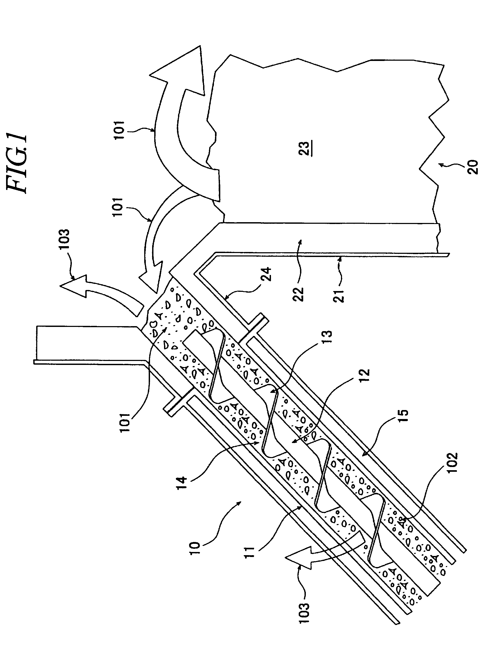
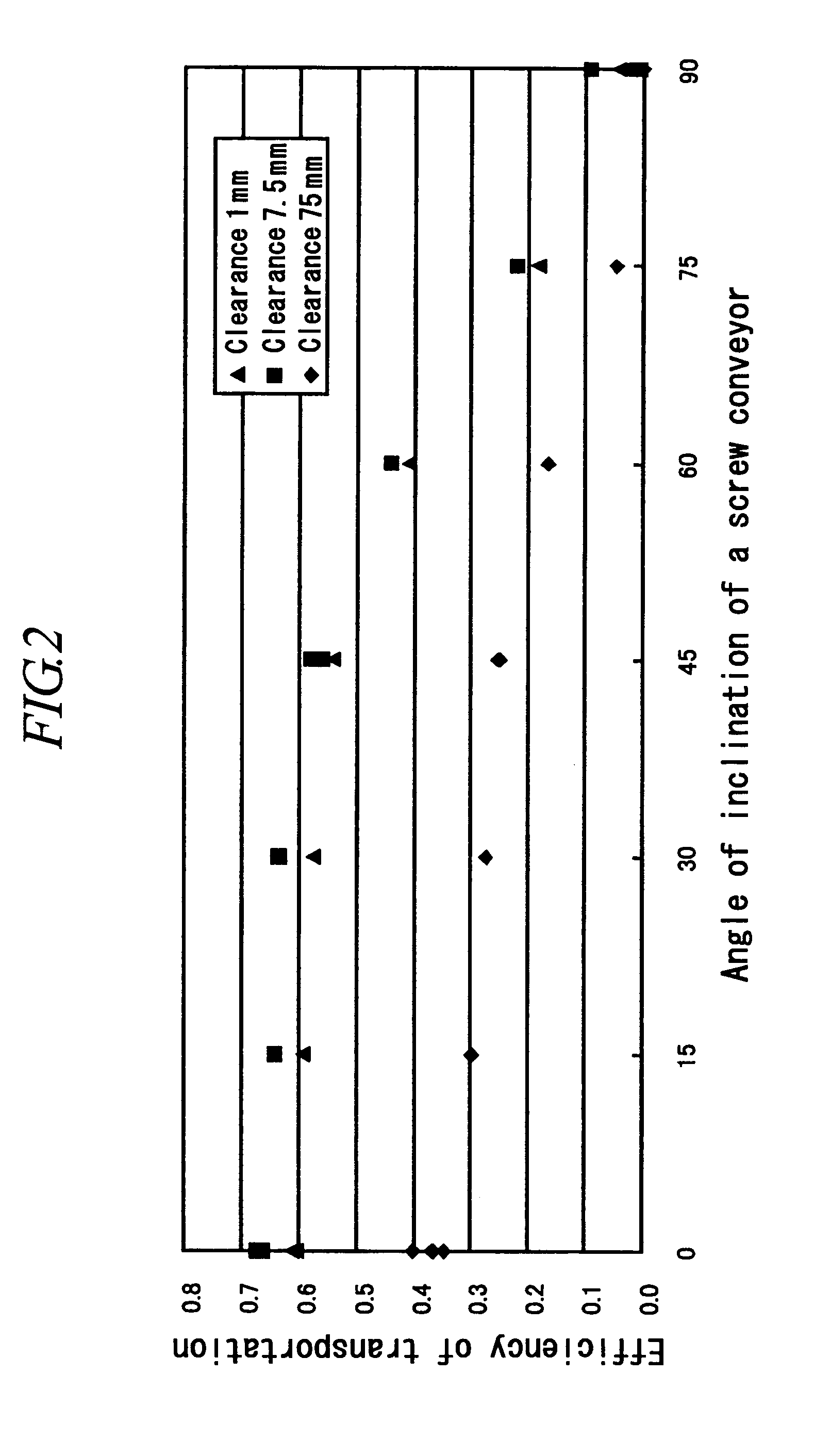
[0128]Here, as a first embodiment according to the invention, a combustible material supplying apparatus for supplying a combustible material to the upper portion of a fluidized bed of a fluidized-bed gasifier chamber or combustion chamber may be characterized in that means for mechanically supplying a raw material with transportation of the combustible material directed upward, at an angle not smaller than a predetermined angle with respect to the horizontal plane.

[0129]Since, as described above, the combustible material supplying apparatus is a means for mechanically supplying a raw material with transportation of the combustible material directed upward, at an angle not smaller than a predetermined angle with respect to the horizontal plane, the material supplying position can be lowered. For example, the height of a building in which the facility is installed can be reduced by a lowered position of the material supplying means such as a crane for carrying combustible materials s...

fourth embodiment

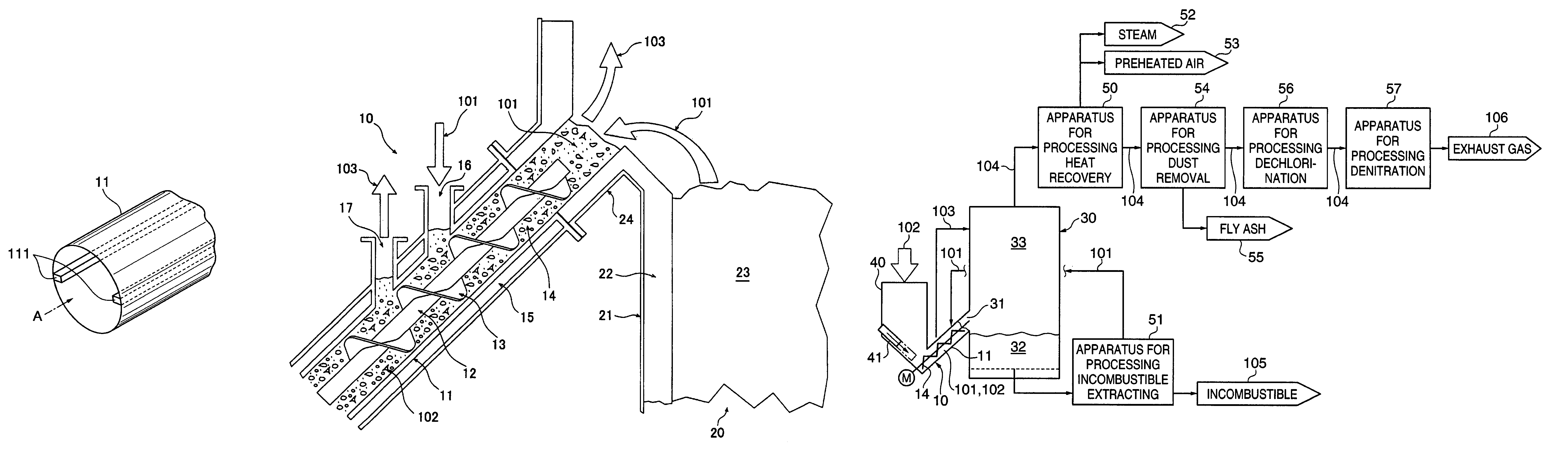
[0134]Further, the invention concerns a facility for gasifying a combustible material having a fluidized-bed gasifier chamber and a combustible material supplying means for supplying a combustible material to the gasifier chamber, and gasifying the combustible material supplied to the upper portion of the fluidized bed by the combustible material supplying means. The combustible material supplying means is a means for mechanically supplying a raw material which is inclined, with transportation of the combustible material directed upward, at an angle not smaller than a predetermined angle with respect to the horizontal plane. A supplying means is provided for filling the means for mechanically supplying a raw material with a bed material to form a fluidized bed of the fluidized-bed gasifier chamber.

[0135]Since, as described above, the combustible material supplying means is a means for mechanically supplying a raw material which is disposed to be inclined, with transportation of the ...

fifth embodiment

[0136]Further, the invention concerns a facility for gasifying a combustible material having a fluidized-bed gasifier chamber and a combustible material supplying means for supplying a combustible material to the gasifier chamber and for gasifying the combustible material supplied to the upper portion of the fluidized bed. The combustible material supplying means is a means for mechanically supplying a raw material which is inclined, with transportation of combustible material directed upward, at an angle not smaller than a predetermined angle with respect to the horizontal plane. A bed material supplying means is provided for filling the means for mechanically supplying a raw material with a bed material to form a fluidized bed of the fluidized bed gasifier chamber. A bypass means is provided which bypasses the gasifier chamber and leads the gas generated by the contact of the combustible material with the bed material in the means for mechanically supplying a raw material, to the ...


PUM


Abstract

A supplying apparatus supplies a combustible material capable of enhancing the sealing effects of a supplying system for supplying a combustible material, such as combustible wastes, to a fluidized-bed chamber, stably supplies a combustible material having an undefined shape, and reduces cost for installation. A facility is also provided for gasifying a combustible material using the supplying apparatus for supplying a combustible material, and a method of gasifying combustible materials is also provided. The supplying apparatus supplies a combustible material onto the fluidized bed of a fluidized-bed gasifier chamber or a fluidized-bed combustion chamber. A screw conveyor is inclined, with transportation of the combustible material directed upward, at an angle of 20 degrees or more and 80 degrees or less with respect to a horizontal plane, causing a bed material to flow into a conveyor casing of the screw conveyor.

Description

BACKGROUND OF THE INVENTION[0001]1. Field of the Invention[0002]The invention relates to a supplying apparatus for supplying a combustible material to a fluidized-bed gasifier chamber or a fluidized-bed combustion chamber, a gasification apparatus for gasifying a combustible material and a method for gasifying combustible materials in a fluidized-bed gasifier chamber or a fluidized-bed combustion chamber for use in a facility for gasifying or incinerating combustible materials such as municipal wastes, industrial wastes, waste plastic, biomass (thinned plants, wood chips, construction scrap wood, sludge, etc.), coal, RDF, wastes of high water contents, and the like.[0003]2. Description of the Related Art[0004]In recent years, a gasification and slagging combustion method has been employed as a treatment method of combustible wastes such as various wastes. In the gasification and slagging combustion method, combustible wastes are pyrolyzed and gasified. If the amount of oxygen suppli...

Claims


Application Information

Patent Timeline
IPC IPC(8): F23K3/00B01J4/00B01J8/24B09B3/00C10J3/00F23CF23C10/22F23G5/00F23G5/027F23G5/30F23G5/44F23J1/02
CPCF23G5/30F23G5/444F23G2201/40F23G2205/121F23G2205/14F23G2208/10Y02W10/40B01J4/00B01J8/24B09B3/00
Inventor MIYOSHI, NORIHISAHASEGAWA, TATSUYANARUSE, KATSUTOSHISAWADA, YASUHIROSASAKI, KOH
Owner EBARA CORP
Learn More