Light-Emitting Device and Method of Manufacturing the Same

Active Publication Date: 2015-07-23
TOYODA GOSEI CO LTD
View PDF11 Cites 32 Cited by
  • Summary
  • Abstract
  • Description
  • Claims
  • Application Information

AI Technical Summary

Benefits of technology

The patent describes a light-emitting device that is reliable, very bright, and has consistent color across the entire device when using a phosphor layer. The patent also explains a method of manufacturing this device.

Problems solved by technology

Thus, a problem may arise that the difference in emission chromaticity between different regions is visually recognized as color unevenness.
In addition, the light-emitting devices disclosed in JP-A-2007-19096, WO 2009 / 069671 and JP-A-2011-134829 may cause a problem that the contact area between the phosphor layer and the light-reflecting member is large and the thermal expansion or heat deterioration of the light-reflecting member is likely to occur due to heat released from the phosphor layer.
The thermal expansion and heat deterioration of the light-reflecting member may cause the deformation or malfunction of the light-emitting device so as to lower the reliability.

Method used


Image

  • Light-Emitting Device and Method of Manufacturing the Same
  • Light-Emitting Device and Method of Manufacturing the Same
  • Light-Emitting Device and Method of Manufacturing the Same

Examples


embodiment

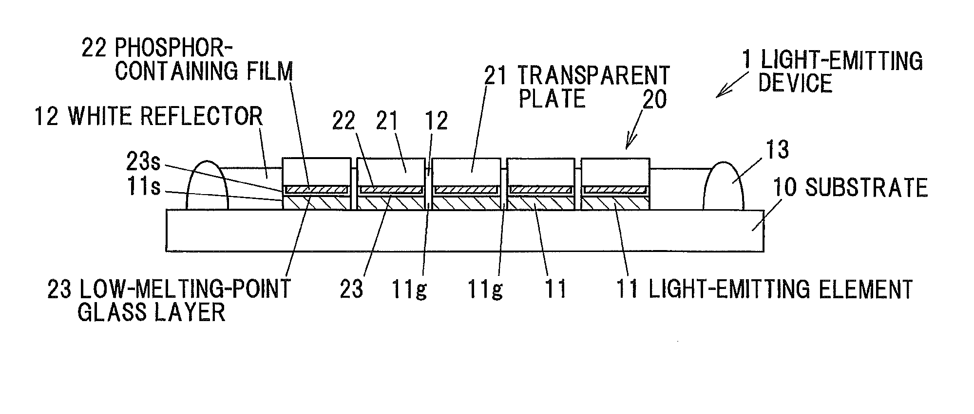
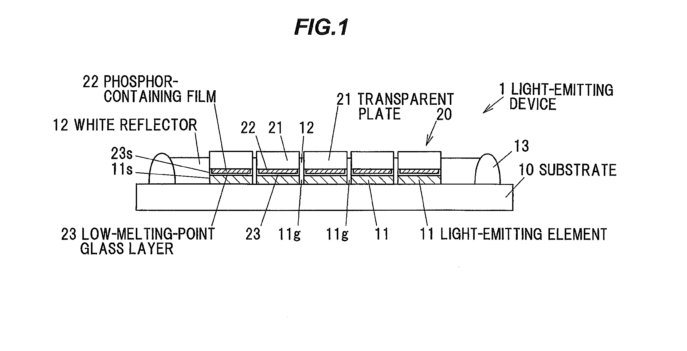
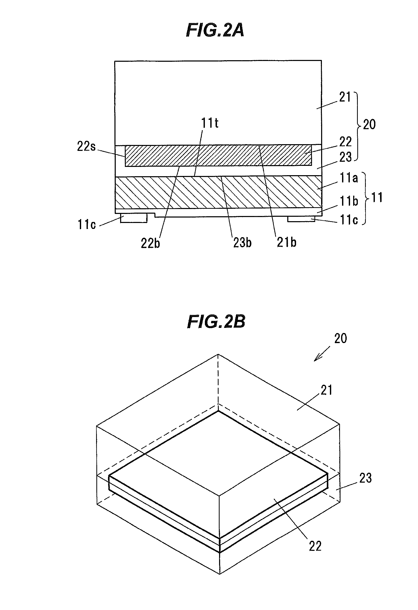
[0041]FIG. 1 is a vertical cross-sectional view showing a light-emitting device 1 in the embodiment. FIG. 2A is a vertical cross-sectional view showing a light-emitting element 11 and a structure 20 of the light-emitting device 1. FIG. 2B is a perspective view showing the structure 20.

[0042]The light-emitting device 1 has plural light-emitting elements 11 face-down mounted on a substrate 10, plural structures 20 provided, one each, on the plural light-emitting elements 11, and a white reflector 12 surrounding the plural light-emitting elements 11 and the plural structures 20.

[0043]The structure 20 includes a transparent plate 21, a phosphor-containing film 22 provided on a lower surface 21b of the transparent plate 21, and a low-melting-point glass layer 23 also provided on the lower surface 21b of the transparent plate 21 so as to cover a lower surface 22b and side surfaces 22s of the phosphor-containing film 22.

[0044]The structures 20 are provided, one each, on the plural light-em...


PUM


Abstract

A light-emitting device includes a plurality of light-emitting elements face-down mounted on a substrate, a plurality of structures each including a transparent plate, a phosphor-containing film provided on a lower surface of the transparent plate and a transparent covering layer provided on the lower surface of the transparent plate so as to cover lower and side surfaces of the phosphor-containing film, the structures being each provided on each of the plurality of light-emitting elements such that a lower surface of the transparent covering layer contacts a top surface of the plurality of light-emitting elements, and a white reflector to cover a side surface of the plurality of light-emitting elements and a side surfaces of the transparent covering layer. At least a portion of a region directly above a gap between the plurality of light-emitting elements is not covered with the phosphor-containing film.

Description

[0001]The present application is based on Japanese patent application No. 2014-008811 filed on Jan. 21, 2014, the entire contents of which are incorporated herein by reference.BACKGROUND OF THE INVENTION[0002]1. Field of the Invention[0003]The invention relates to a light-emitting device and a method of manufacturing the light-emitting device.[0004]2. Description of the Related Art[0005]A light-emitting device is known which has a phosphor layer with a phosphor included therein and in which the side surface of a light-emitting element is covered with a light-reflecting member (see, e.g., JP-A-2007-19096, WO 2009 / 069671 and JP-A-2011-134829). In the light-emitting device, light laterally emitted from the light-emitting element is reflected by the light-reflecting member so as to improve luminance.[0006]JP-A-2007-19096 discloses a light-emitting device in which a flip-chip mounted LED element, except a light-extracting surface, is covered with a coating material including light-reflec...

Claims


Application Information

Patent Timeline
IPC IPC(8): F21K99/00
CPCF21K9/56F21K9/90F21K9/54H01L25/0753H01L24/83H01L24/95H01L33/505H01L33/507H01L33/60
Inventor WADA, SATOSHIKAWAOKA, AYA
Owner TOYODA GOSEI CO LTD
Why Eureka
Try Eureka