Multiple sample chromatography using a stochastic injection technique

a stochastic injection and chromatography technology, applied in the field of high sensitivity chromatography using stochastic injection techniques, can solve the problems of requiring extra power and space, affecting human health and ecosystem, and using this extra component, so as to achieve the effect of better approximation of individual chromatograms

Active Publication Date: 2015-07-23
INSTITUT FR DES SCI & TECH DES TRANSPORTS DE LAMENAGEMENT & DES RESEAUX +1
View PDF4 Cites 6 Cited by
  • Summary
  • Abstract
  • Description
  • Claims
  • Application Information

AI Technical Summary

Benefits of technology

The technical effects of this patent are to reduce the time required for analyzing multiple samples using chromatography and to improve the accuracy of the data produced by the chromatography system.

Problems solved by technology

Volatile organic compounds (VOCs) are major indoor and outdoor pollutants that can seriously affect human health and ecosystem.
However, the use of this extra component has several drawbacks such as requiring extra power and space, and increasing the measurement time significantly.
However a major drawback of the method described in U.S. Pat. No. 8,297,135 B2 is that one sample is injected at a time.
Besides, such technique produces chromatograms having poor signal-to-noise ratios which lead to inaccurate analysis of the corresponding samples.

Method used


Image

  • Multiple sample chromatography using a stochastic injection technique
  • Multiple sample chromatography using a stochastic injection technique
  • Multiple sample chromatography using a stochastic injection technique

Examples


first embodiment

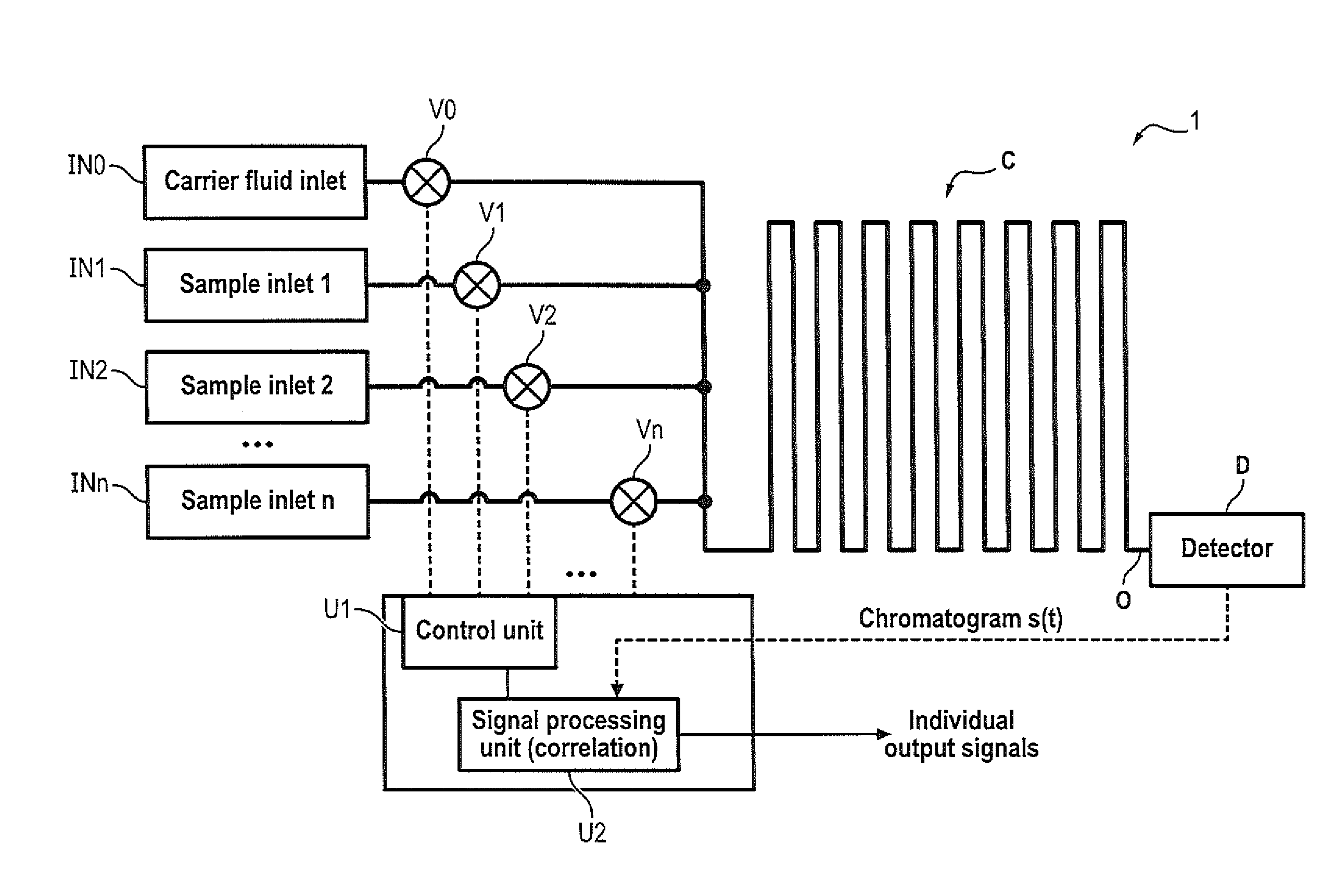
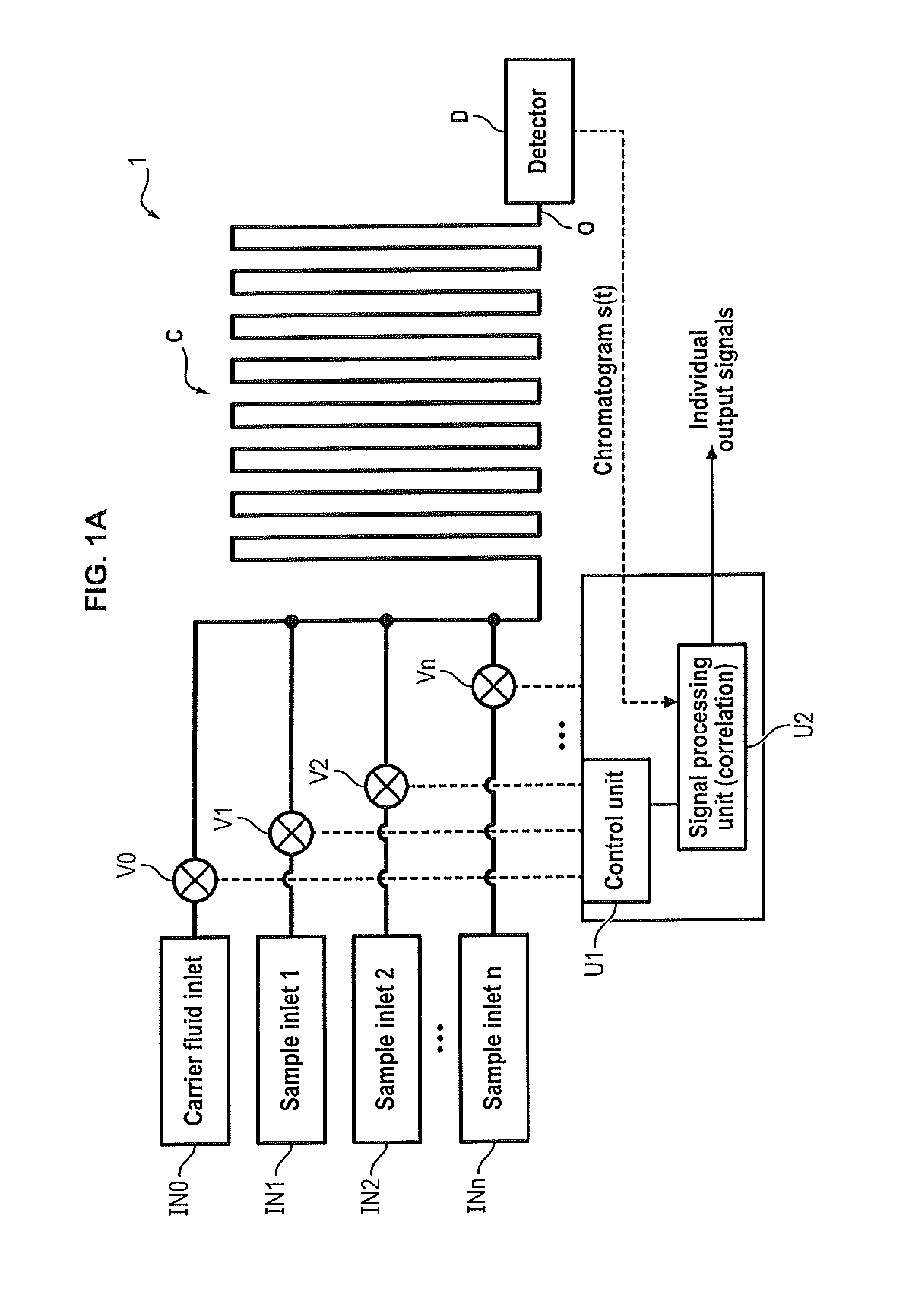
[0090]FIG. 1A shows a chromatography device 1 for analyzing n independent samples simultaneously.

[0091]The chromatography device 1 comprises a plurality of sample inlets IN1 to INn, each sample inlet INi being designed for inputting a respective fluid sample hereafter referred to as “sample”. The device 1 may also comprise an additional carrier inlet INC designed for inputting a carrier fluid for carrying the samples inputted through inlets IN1 to INn.

[0092]Different types of samples may be inputted through each inlet IN0-In: a gas or a liquid.

[0093]The device 1 also comprises a plurality of on-off valves V0-Vn, each valve Vi acting as an injector arranged at a corresponding inlet INi for selectively opening and closing the inlet INi.

[0094]The device 1 also comprises one outlet O connected to all sample inlets IN0-INn, and a chromatography column extending between the inlets and the single outlet O. Thus, fluidic samples coming from inlets IN1 to INn carried thanks to the carried fl...

second embodiment

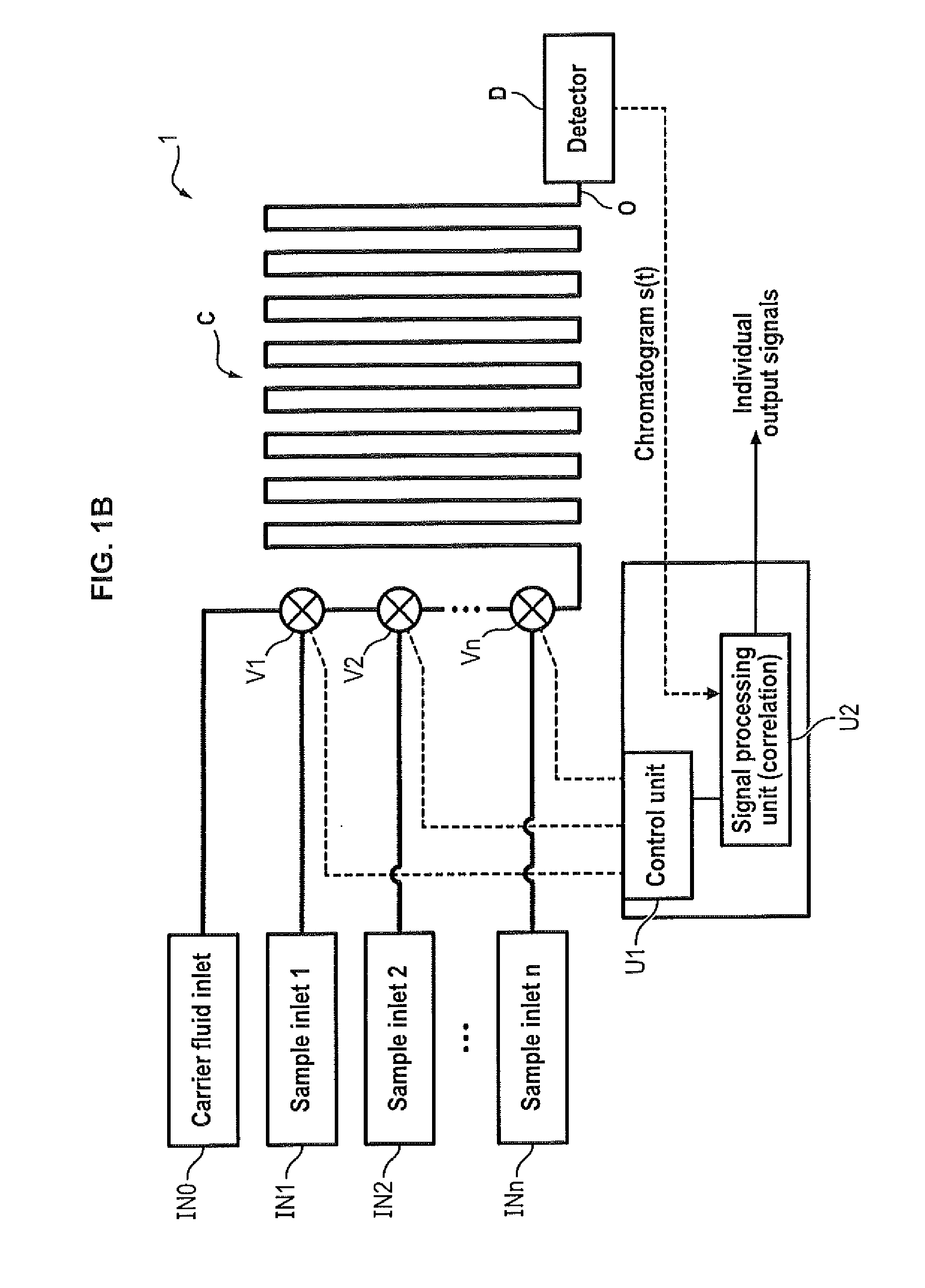
[0098]In a second embodiment depicted on FIG. 1B, multi-port rotary valves are used as injectors in series operation. In this operation mode, the carrier gas line is shared by all the injectors. That means that when a sample is injected upstream, the said sample goes through all the valves before reaching the column. Each valve is controlled independently by the control unit.

third embodiment

[0099]In a third embodiment depicted on FIG. 1C, presents an example of an injector in series operation based on two 2-position 6-port rotary valves using a sample loop. Such rotary valves are often used to inject a controlled amount of gas corresponding to the internal volume of the sample loop: in their normal position, the gas vector flows directly to the output while the sample flows in the sample loop. When the position of the valve is switched, the carrier gas flows through the sample loop and pushes the sample to the output. In this example, the carrier gas line is connected to a first rotary valve, and the output of this first rotary valve is then connected to the carrier gas input of the second valve. When the position of any valve is switched, the sample present in the corresponding sample loop is pushed to the column. In this configuration, one must be careful to operate the valve so that no sample injected upstream is disturbed by the switching of a valve downstream.


PUM

PropertyMeasurementUnit
period of timeaaaaaaaaaa
timeaaaaaaaaaa
lengthaaaaaaaaaa

Abstract

The invention relates to a method for simultaneously analyzing at least two samples using a chromatography device comprising a chromatography column having an inlet and an outlet, and at least one detector placed at the outlet of the chromatography column, the method comprising steps of: injecting fractions of each independent sample at the inlet of the chromatography column, the fractions of each independent sample being injected according to a specific injection timing sequence derived from a pseudo-random binary sequence associated with said independent sample; recording a signal generated by said detector for a period of time at least equal to a duration of the longest of the specific injection timing sequences; cross-correlating the recorded signal and a derived correlation function, said derived correlation function being derived from the pseudo-random binary sequence associated with one of the independent samples, so as to obtain an individual correlogram signal specific to said independent sample; and analyzing data of interest of the individual correlogram signal so as to obtain an output signal indicative of a composition of the sample.

Description

TECHNICAL FIELD[0001]The invention relates to a method for simultaneously analyzing at least two samples using chromatography.[0002]The invention deals more specifically with high sensitivity chromatography using stochastic injection techniques.BACKGROUND OF THE INVENTION[0003]Volatile organic compounds (VOCs) are major indoor and outdoor pollutants that can seriously affect human health and ecosystem. In order to ensure the safety of our environment, it is important to be able to measure and control the concentration of such gases with both high selectivity and sensitivity, and at multiple locations. Real-time monitoring of air pollution would be possible by processing data coming from multiple, fast and accurate sensors such as micro gas chromatographs (referred to as “GC” in the following).[0004]Gas chromatography is one of the most popular analytical chemistry tools for the analysis of volatile compounds. This technique consists in detecting peaks corresponding to vapors that ar...

Claims


Application Information

Patent Timeline
Patent Type & Authority Applications(United States)
IPC IPC(8): G01N30/16G01N30/86
CPCG01N30/16G01N30/8651G01N2030/027G01N2030/025G01N2030/167G01N30/86
Inventor ANGELESCU, DANCESAR, WILLIAMBOUROUINA, TARIK
Owner INSTITUT FR DES SCI & TECH DES TRANSPORTS DE LAMENAGEMENT & DES RESEAUX
Why Eureka
Try Eureka