Supercharge Your Innovation With Domain-Expert AI Agents!

Moving object detection method

Active Publication Date: 2015-07-23
IHI CORP
View PDF1 Cites 2 Cited by
  • Summary
  • Abstract
  • Description
  • Claims
  • Application Information

AI Technical Summary

Benefits of technology

The present invention aims to provide a method for detecting moving objects in images based on signal levels, while reducing the impact of noise components in the background area behind the detection object. The technical effect of the invention is an improved accuracy in detecting moving objects.

Problems solved by technology

However, noise components occurring when the captured images are quantized into the image signals, such as thermal noise of photodetectors and readout noise of the CCD elements which occur in the CCD camera, are included not only in the image signals before being subjected to the dark correction, the flat correction and the like, but also in image signals used to determine the correction values.
For this reason, when the image signals before the correction are corrected using the correction values, the noise components occurring in association with the quantization of the captured images are added to the image signals after being subjected to the dark correction, the flat correction and the like, and accordingly decrease the accuracy with which to detect the moving object.

Method used


Image

  • Moving object detection method
  • Moving object detection method
  • Moving object detection method

Examples


Embodiment Construction

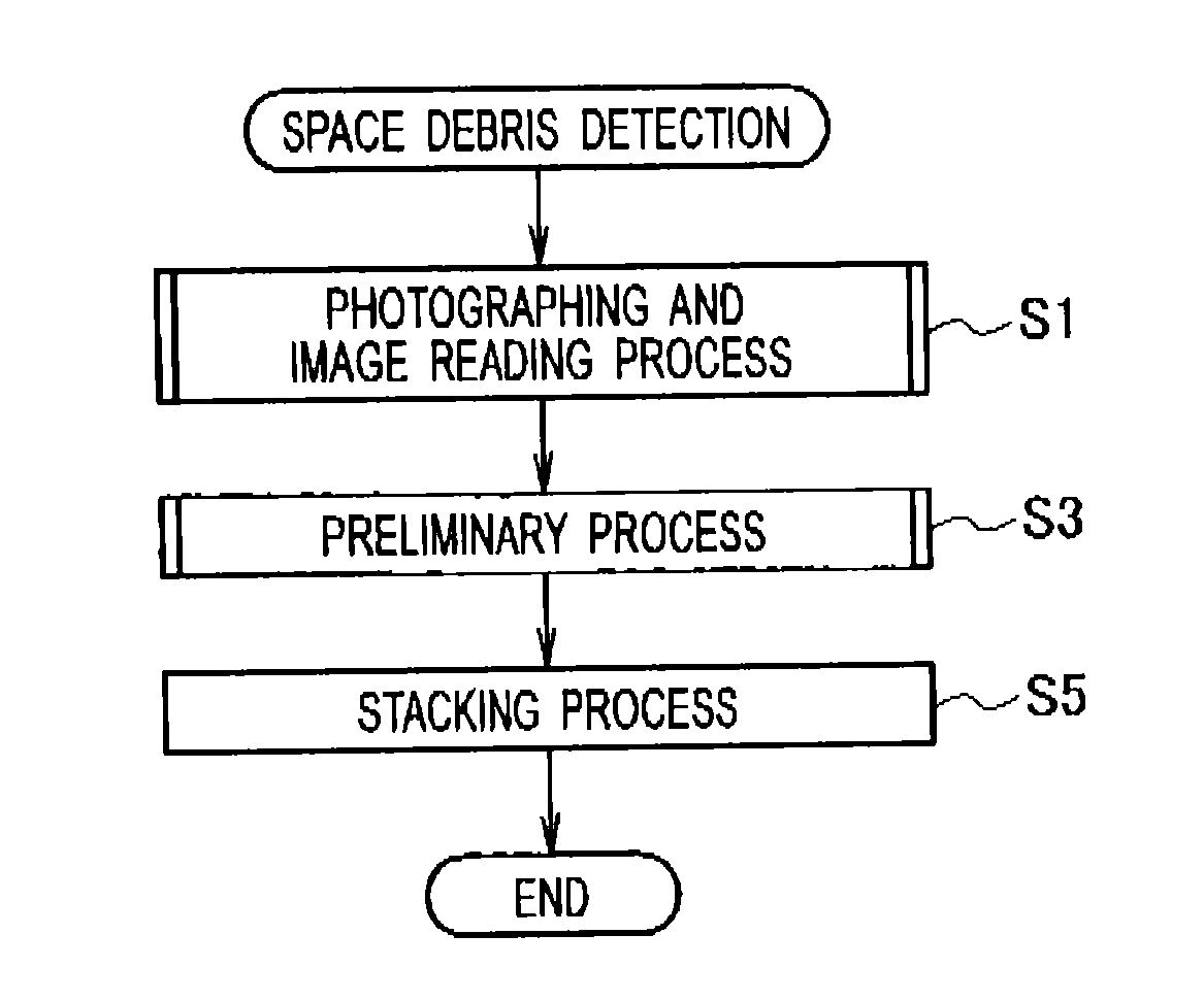
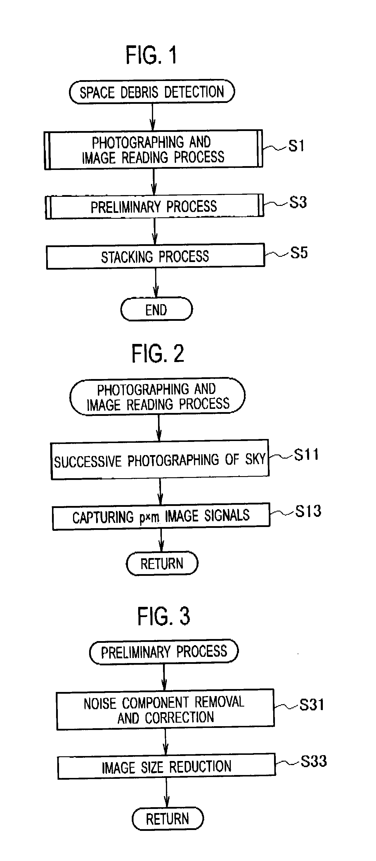
[0027]Referring to the drawings, descriptions will be provided for an embodiment in which a moving object detection method of the present invention is applied to detection of space debris from photographed celestial images.

[0028]The moving object detection method of the embodiment is designed to detect space debris as a moving object being an observation object from the photographed celestial images. A described in a flowchart of FIG. 1, this method is designed to perform a photographing (capturing) and image reading process step (step S1), a preliminary process step (step S3) and a superposition process step (step S5).

[0029]As shown in the flowchart of FIG. 2, the photographing and image reading process step (step S1 in FIG. 1) begins with repeatedly making a series of photographs of a space (the sky), including the geostationary orbit of space debris, for a predetermined length of exposure time at constant time intervals (step S11). Subsequently, the image reading process step (st...


PUM


Abstract

When correction values are respectively determined for noise components of “OFFSET COMPONENT OF CCD ELEMENT”, “GRADATION COMPONENT OF BACKGROUND LIGHT” and “OFFSET COMPONENT OF OPTICAL SYSTEM”, the pixel values including as less of these noise components as possible are evaluated. The evaluated pixel values include a noise component of “THERMAL NOISE PLUS READOUT NOISE COMPONENT” which is superposed onto the pixel values. With this taken into consideration, a moving object detection method of an embodiment photographs multiple images of a moving object being an observation object with a photographic area fixed, selects the smallest pixel value in each group of corresponding pixels across the images from image signals representing the images, evaluates image signals including as less of the four noise components as possible by using the smallest pixel value as the correction value for the four noise components.

Description

CROSS REFERENCE TO RELATED APPLICATION[0001]The present application is a continuation application of International Application No. PCT / JP2013 / 073941, filed Sep. 5, 2013, which claims priority to Japanese Patent Application No. 2012-197531, filed Sep. 7, 2012. The contents of these applications are incorporated herein by reference in their entirety.BACKGROUND OF THE INVENTION[0002]1. Field of the Invention[0003]The present invention relates to a method of detecting a moving object from captured images.[0004]2. Description of the Related Art[0005]Space debris is an out-of-service artificial object which orbits the Earth. A detection of the existence of the space debris is important for smooth operation of spacecraft (artificial satellites, space stations, space shuttles and the like). One method among conventional space debris detection methods determines the existence of space debris by extracting high-luminance parts respectively from images captured by a CCD (charge coupled device)...

Claims


Application Information

Patent Timeline
IPC IPC(8): G06K9/00G06T5/00G06T5/10
CPCG06K9/00624G06T5/10G06T5/002G06T2207/10016G06T2207/20182B64G1/68B64G3/00H04N5/144H04N25/63H04N25/671G06T5/70
Inventor BANNO, HAJIME
Owner IHI CORP
Features
  • R&D
  • Intellectual Property
  • Life Sciences
  • Materials
  • Tech Scout
  • Unparalleled Data Quality
  • Higher Quality Content
  • 60% Fewer Hallucinations
Learn More