
Unified memory systems and methods

a memory system and memory technology, applied in the field of memory configuration, can solve problems such as pointer collision or overlap, complex addition of various capabilities to a complex system, and undesirable impacts

Active Publication Date: 2015-07-23
NVIDIA CORP
View PDF7 Cites 24 Cited by
  • Summary
  • Abstract
  • Description
  • Claims
  • Application Information

AI Technical Summary

Benefits of technology

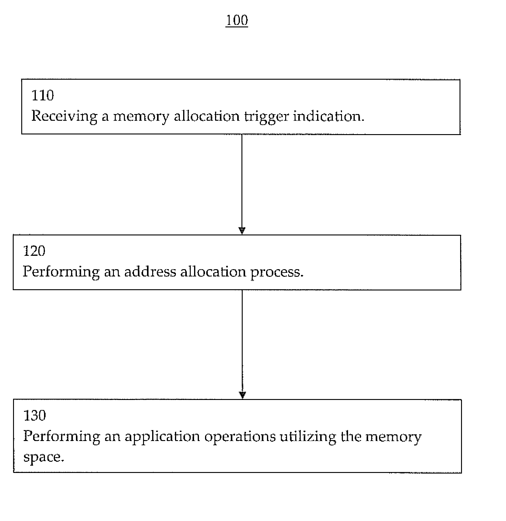
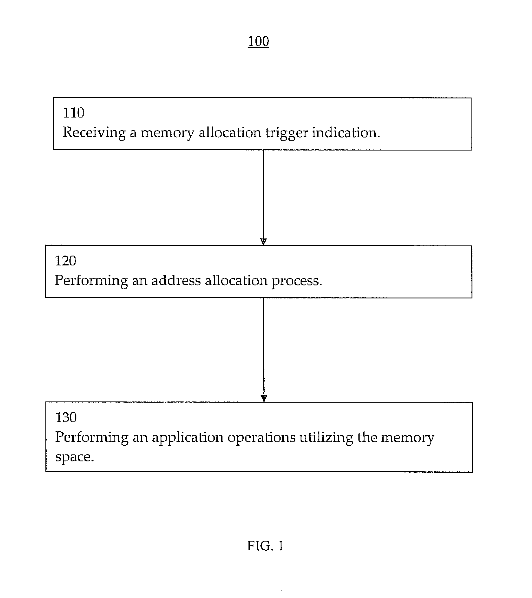
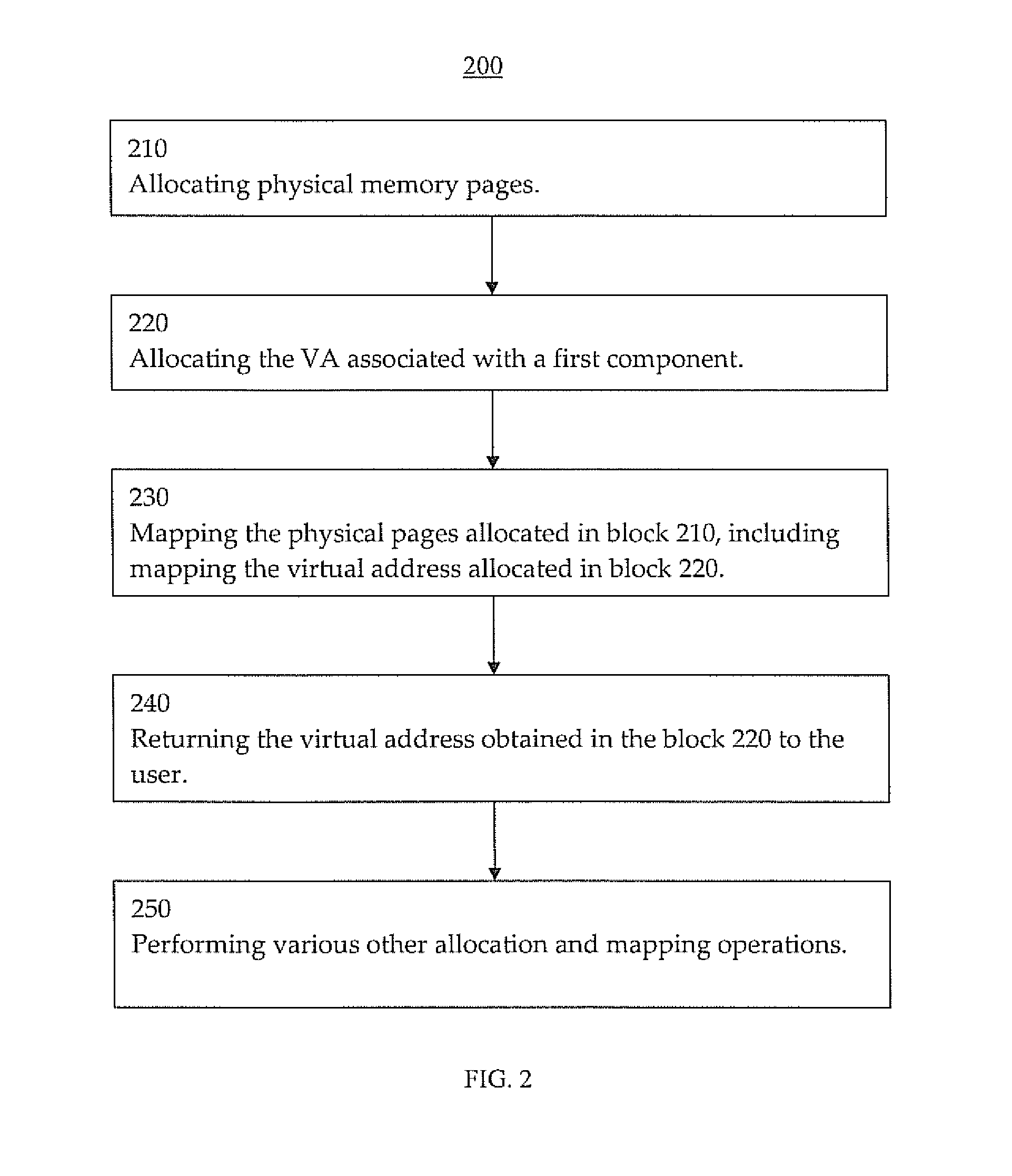
The present invention allows for efficient use of virtual addresses across different components in a computer system. This is achieved by combining the use of the operating system's allocation function with the allocation of graphics processing unit (GPU) driver mappings. This helps prevent collisions between the virtual addresses allocated to the CPU and the GPU. The allocation process involves mapping physical memory pages to virtual addresses allocated to the first component (e.g., CPU) using an element associated with the second component (e.g., GPU driver). The virtual address allocated to the first component is returned to the user. Overall, this results in a more efficient and effective use of unified virtual addresses in computer systems.

Problems solved by technology

However, adding various capabilities to a complex system can be complicated and traditional attempts at implementing various features (e.g., conventional attempts at utilizing virtual addresses across various components of a system, etc.) can have undesirable impacts.
These are often distinct virtual address (VA) spaces setup by different software components and can potentially lead to pointer collision or overlap.
It is usually difficult to determine if a given particular virtual address (e.g., associated with a pointer, etc.) belongs to the CPU VA space, GPU VA space, or both.
The various conventional approaches that attempt to handle virtual addresses and pointer tracking typically have a number of problems.
However, this approach often has a number of drawbacks including possible waste of CPU VA space if a large chunk is reserved initially but the actual amount of space that is required or utilized is much less.
Given the total CPU VA space available is relatively small, reserving large chunks of CPU VA space for the GPU can result in less or inadequate VA space remaining available for operations of the other components (e.g., CPU, etc.) and can lead to lower system utilization.

Method used


Image

  • Unified memory systems and methods
  • Unified memory systems and methods
  • Unified memory systems and methods

Examples


Embodiment Construction

[0029]Reference will now be made in detail to the preferred embodiments of the invention, examples of which are illustrated in the accompanying drawings. While the invention will be described in conjunction with the preferred embodiments, it will be understood that they are not intended to limit the invention to these embodiments. On the contrary, the invention is intended to cover alternatives, modifications and equivalents, which may be included within the spirit and scope of the invention as defined by the appended claims. Furthermore, in the following detailed description of the present invention, numerous specific details are set forth in order to provide a thorough understanding of the present invention. However, it will be obvious to one ordinarily skilled in the art that the present invention may be practiced without these specific details. In other instances, well known methods, procedures, components, and circuits have not been described in detail as not to unnecessarily o...


PUM


Abstract

The present invention facilitates efficient and effective utilization of unified virtual addresses across multiple components. In one embodiment, the presented new approach or solution uses Operating System (OS) allocation on the central processing unit (CPU) combined with graphics processing unit (GPU) driver mappings to provide a unified virtual address (VA) across both GPU and CPU. The new approach helps ensure that a GPU VA pointer does not collide with a CPU pointer provided by OS CPU allocation (e.g., like one returned by “malloc” C runtime API, etc.).

Description

RELATED APPLICATIONS[0001]This application claims the benefit of and priority to:[0002]provisional application 61 / 929,496 (Attorney docket number NVID-P-SC-1649) entitled “Unified Memory Systems and Methods” filed Jan. 20, 2014;[0003]provisional application 61 / 965,089 (Attorney docket NVID-P-SC-16453RUS0) entitled “Unified Memory Systems and Methods” filed Jan. 21, 2014; and[0004]provisional application 61 / 929,913 (Attorney docket NVID-P-BG-13-1449US0CS) entitled “Inline Parallelism and Re-targetable Parallel Algorithms” filed Jan. 21, 2014;which are all incorporated herein by reference.FIELD OF THE INVENTION[0005]The present invention relates to the field of memory configuration. In one embodiment, virtual addressing associated with unified memory is implemented with pointer collision avoidance or mitigation.BACKGROUND OF THE INVENTION[0006]Electronic systems and devices have made a significant contribution towards the advancement of modern society and are utilized in a number of a...

Claims


Application Information

Patent Timeline
Patent Type & Authority Applications(United States)
IPC IPC(8): G06T1/60G06F12/10G06T1/20
CPCG06T1/60G06F12/109G06T1/20G06F9/5016
Inventor RAO, AMITSRIVASTAVA, ASHISHKINI, YOGESHDOUILLET, ALBANGERFIN, GEOFFREYKAUSHIK, MAYANKSHULGA, NIKITAVENKATARAMAN, VYASFONTAINE, DAVIDHAIRGROVE, MARKJAROSZYNSKI, PIOTRJONES, STEPHENKINI, VIVEK
Owner NVIDIA CORP
Learn More