

Actuator device
a technology of actuator and spring force, which is applied in the field of actuator, can solve the problems of inability to reliably implement actuation tasks, limited usability in the general practice, and increase the spring force acting on the expansion unit to restore the spring force, etc., and achieves the effect of simple production
- Summary
- Abstract
- Description
- Claims
- Application Information
AI Technical Summary
Benefits of technology
Problems solved by technology
Method used
Image

Examples
first embodiment
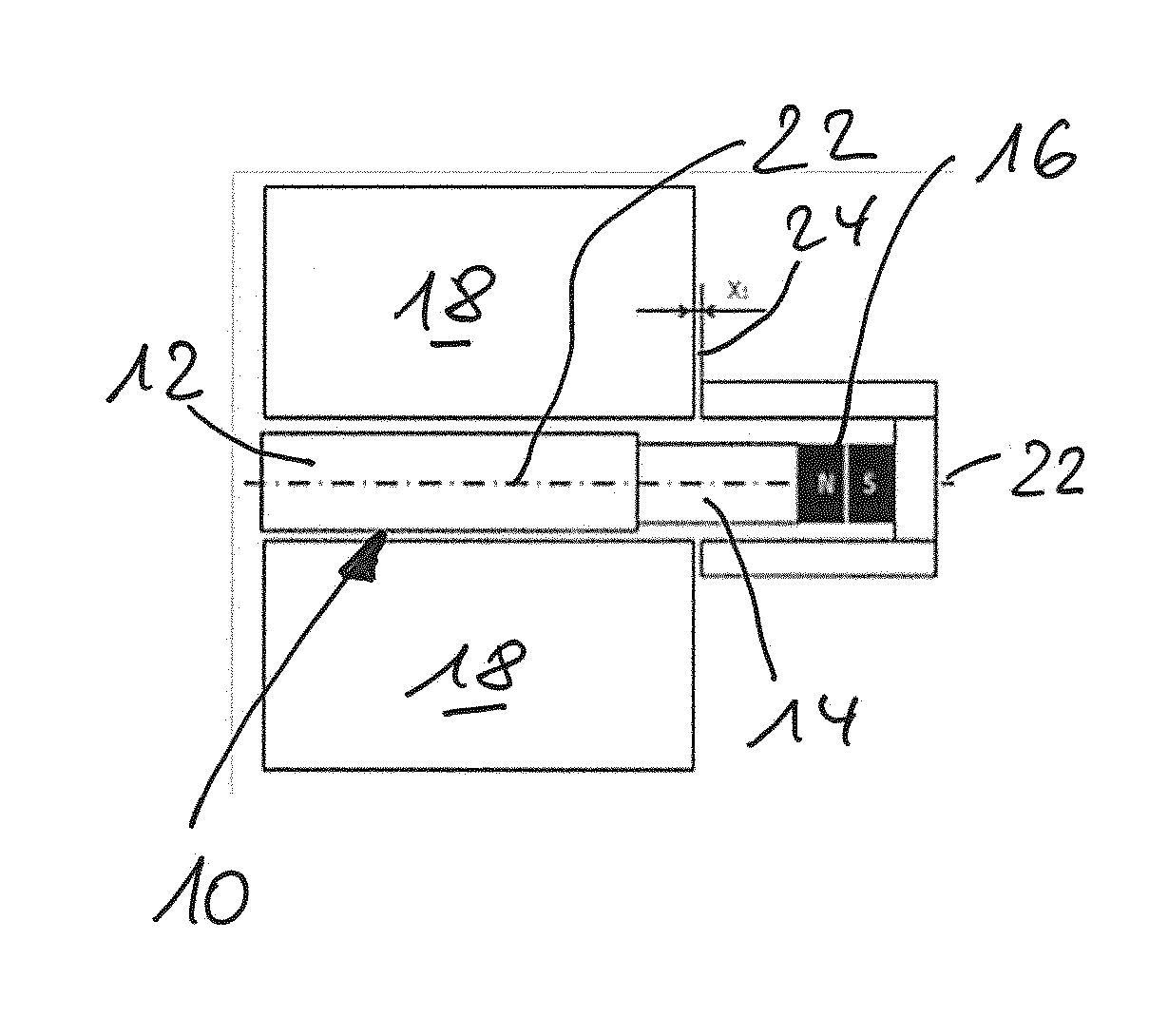
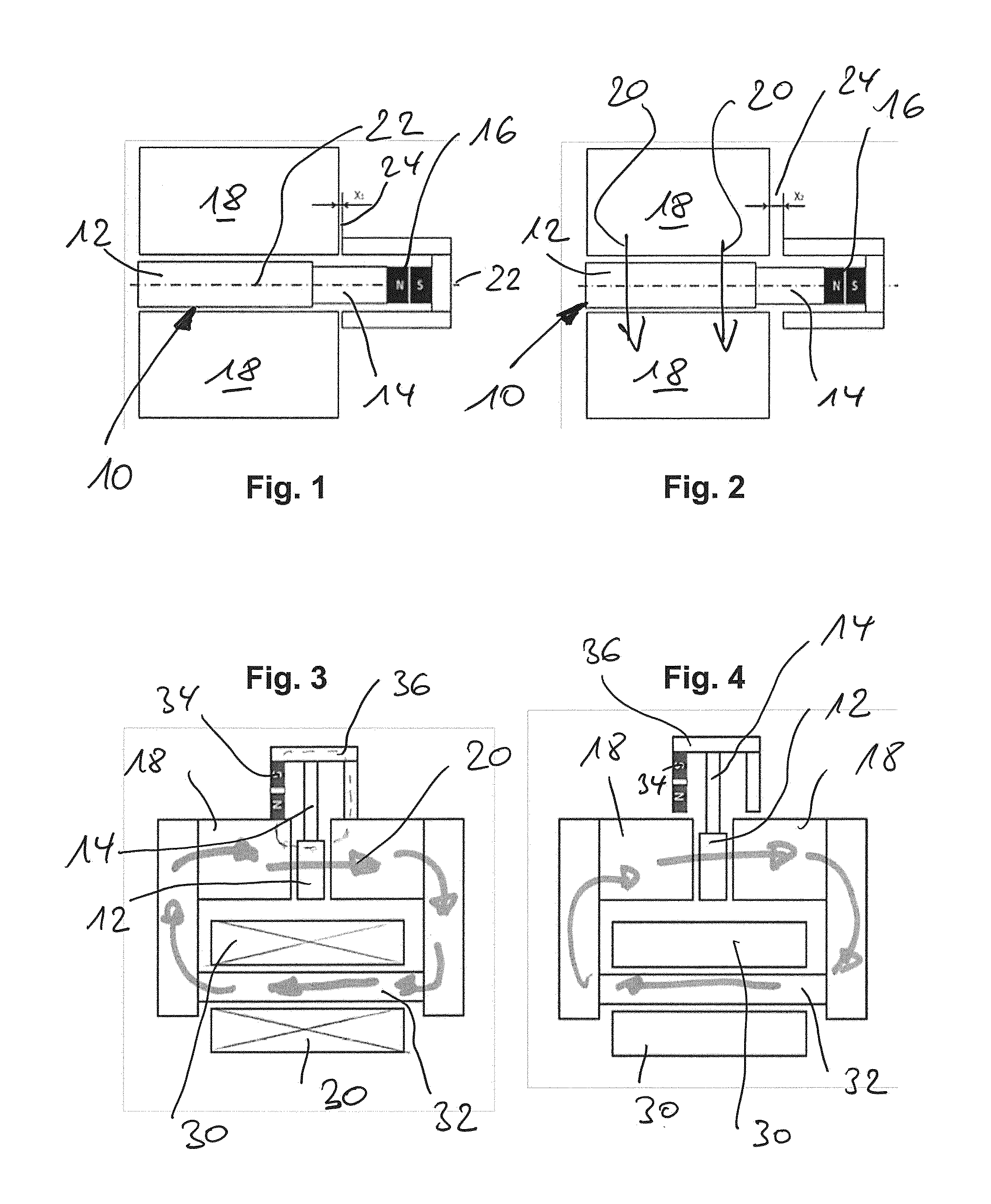
[0027]FIG. 1 shows a fragmented illustration (without showing a coil device for generating the electromagnetic field) of the present invention.
[0028]An expansion unit 10 consisting of an elongate shape memory alloy crystal 12, a magnetically non-conductive section 14 adjoining thereto, and an axially magnetised permanent magnet body 16 is guided in the manner of a tappet inside a flux-conductive stator 18. Said flux-conductive stator conducts an electromagnetic flux of the coil means (not shown) in a transverse direction along an arrow direction 20 through the MSM crystal 12, to effect an expansion movement in the axial direction, corresponding to the axis 22 shown.
[0029]As can also be seen in FIGS. 1, 2, the permanent magnet body 16 is assigned a cup-shaped flux-conducting element 24, which closes a permanent-magnetic flux circuit via the stator 18, forming an air gap 24 (distance x1 in the starting position of FIG. 1).
[0030]In contrast to the non-energised coil state of FIG. 1, FI...
second embodiment
[0031]FIGS. 3 and 4 show the present invention, in a somewhat more detailed configuration and with additionally shown coil unit 30, which is provided around a flux-conductive section 32 and introduces the transversely running electromagnetic flux 20 into the flux-conducting elements (stator) 18 in the manner shown. In the exemplary embodiment of FIGS. 3, 4, in variance from the first exemplary embodiment, the flux-conducting element 36 assigned to the permanent magnet body 34 (again axially magnetised) is configured in such a manner that the permanent magnet body 34 is partially accommodated in the lateral face thereof.
[0032]The arrows drawn schematically in the illustration of FIGS. 3, 4 also show that the flux-conducting section 32 closes the permanent-magnetic flux circuit.
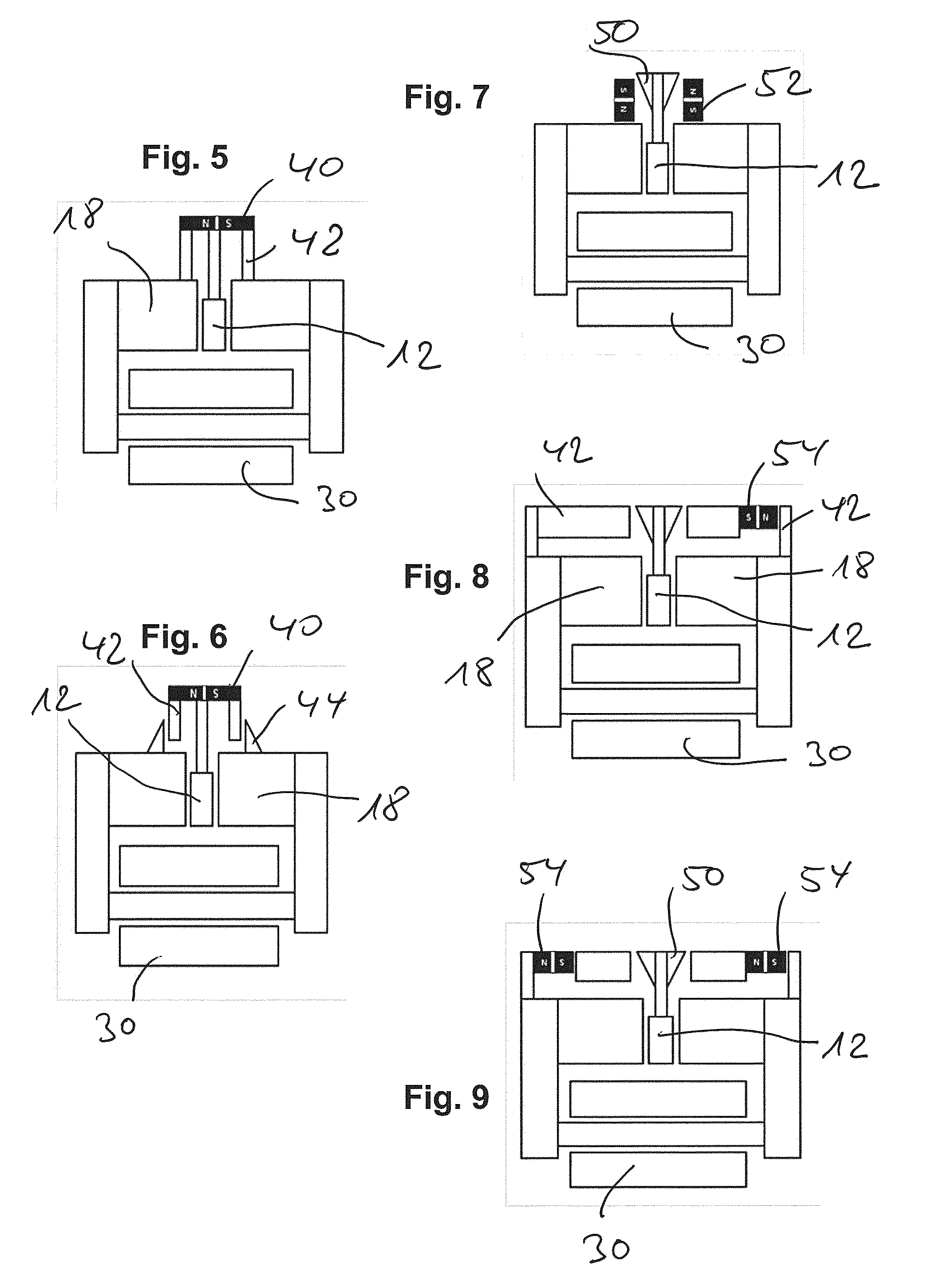
[0033]FIGS. 5 and 6 show further variants of a permanent magnet unit on the armature side (i.e. provided on the expansion unit itself and movable with same), in FIGS. 5, 6 in the form of a disc-shaped or rod-sh...
PUM
 Abstract
Description
Claims
Application Information