
Compact robotic wrist

a robotic wrist and compact technology, applied in the field of robotic tools and end effectors, can solve the problems of insufficient straight rigid tools

Active Publication Date: 2015-07-30
SRI INTERNATIONAL
View PDF0 Cites 98 Cited by
  • Summary
  • Abstract
  • Description
  • Claims
  • Application Information

AI Technical Summary

Benefits of technology

The patent is addressing the need for better robotic tools and end effectors that can improve efficiency and performance on the job. These tools should be able to work in tight spaces, perform complex operations, and minimize the impact on the worksite. This is important because existing tools have limitations and can make it difficult to complete tasks. The patent proposes to develop better tools to overcome these issues.

Problems solved by technology

Straight rigid tools are insufficient in some surgical settings, for example when an organ or anatomical structure is between the incision point or port (e.g., the location the tool enters into the body) and the tissue to be operated upon, because the straight shaft is unable to reach around the organ or anatomical structure to access the tissue.
Another deficiency of straight rigid tools is that they are not well suited for use in what is referred to as single port surgery, where more than one tool is introduced through a single surgical incision or port, which is sometimes desirable to limit trauma to the patient.
To interact cooperatively, the tools need to converge on the operative space from different angles, which straight rigid tools are not well suited for.
With respect to flexible tools, such as curved or bent tools, these tools overcome some of the access and maneuverability issues of straight rigid tools discussed above, but also have deficiencies.
One shortcoming of flexible tools is that they typically are not rigid enough to resist bending loads during surgical procedures.
These flexible tools also have shortcomings, such as being unable to achieve sufficient rigidity to withstand bending loads once bent during a surgical procedure.
Each cable can be arranged such that the relative tension between the two sides of each cable may result in a yaw motion.

Method used


Image

  • Compact robotic wrist
  • Compact robotic wrist
  • Compact robotic wrist

Examples


Embodiment Construction

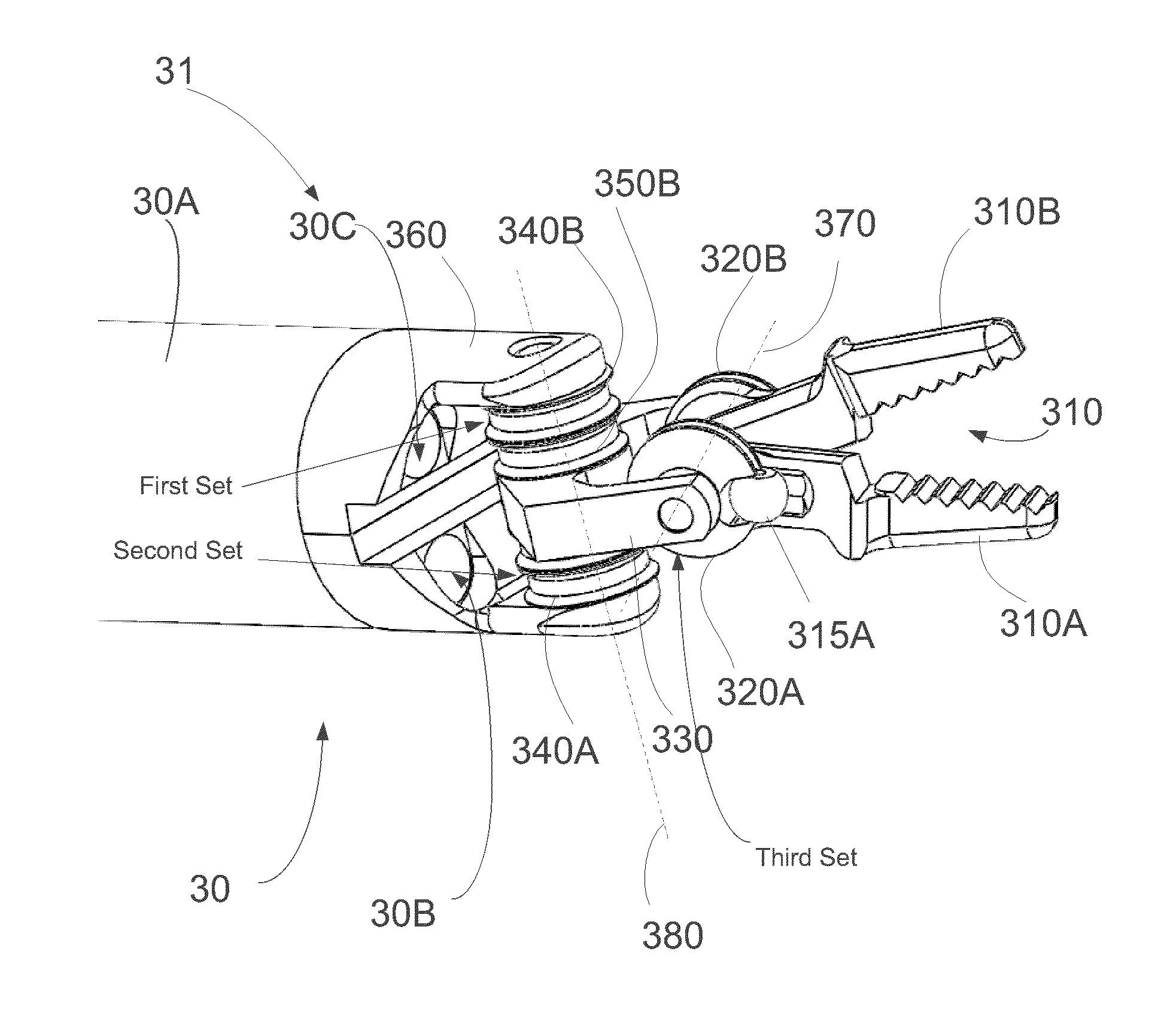
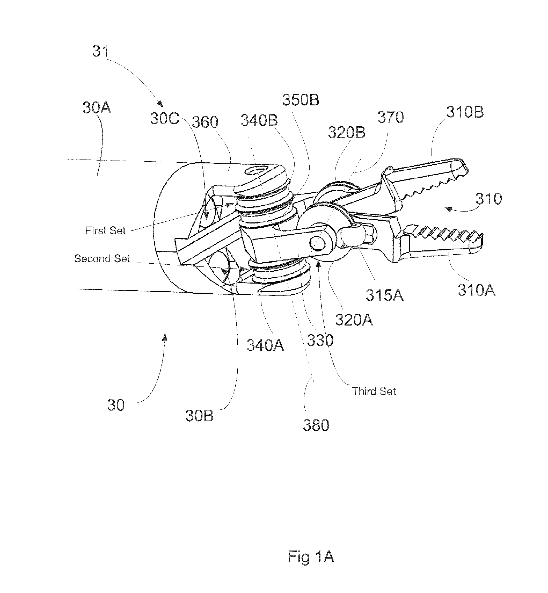
[0089]Described below are embodiments of tools, such as surgical tools, that have various advantages over on-market tools. At least some of the embodiments of tools described herein advantageously provide for less occlusion of the worksite, thereby allowing the operator improved visualization of the worksite. At least some of the embodiments of tools described herein provide for enhanced ability (e.g., of an operator of the tool, of a surgeon operating a tool) to perform complex operations by, for example, reducing the diameter of the wrist of the tool. At least some embodiments of tools describe herein provide enhanced ability to work in areas where access is limited (e.g., a smaller workspace), which can be made possible at least in part by a reduction in the diameter of the wrist of the tool.

[0090]In some embodiments disclosed below, a tool can include an end effector coupled to a tool shaft via a wrist, where the wrist allows for multi-axial motion (e.g., movement in pitch and y...


PUM


Abstract

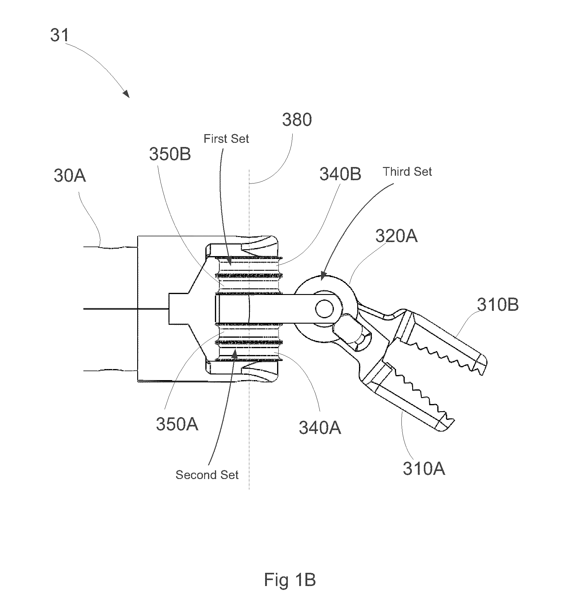
An integrated multiaxial wrist and grasper system for use in a robotic tool can yaw, pitch and grasp via actuation of four independent cable ends of four cables. The tool includes a drive mechanism that effects movement of the multiaxial wrist and grasper via actuation of the cables that extend between the drive mechanism and the wrist.

Description

INCORPORATION BY REFERENCE TO ANY PRIORITY APPLICATIONS[0001]This application is a continuation of U.S. patent application Ser. No. 14 / 388,208, filed Sep. 25, 2014, which is a U.S. national phase filing of PCT Application No. PCT / US2014 / 026721, filed Mar. 13, 2014, which claims the priority benefit under 35 U.S.C. §119(e) of U.S. Provisional Application No. 61 / 781092 filed Mar. 14, 2013, and U.S. Provisional Application No. 61 / 791248 filed Mar. 15, 2013. The disclosures of the PCT Application and the Provisional Applications are each hereby incorporated by reference in their entirety and should be considered a part of this specification.STATEMENT REGARDING FEDERALLY SPONSORED R&D[0002]This invention was made with Government support under Government contract number HSHQDC-10-C-00118, awarded by the Department of Homeland Security. The Government has certain rights in this invention.BACKGROUND[0003]1. Field[0004]Robotic end effectors allow robots to manipulate objects. The present app...

Claims


Application Information

Patent Timeline
Patent Type & Authority Applications(United States)
IPC IPC(8): B25J17/02B25J15/00A61B19/00B25J15/02
CPCB25J17/02B25J15/0286B25J15/0028A61B19/2203A61B2019/2246Y10S901/36Y10S901/38A61B2019/2234A61B2019/2242Y10S901/29A61B2034/715A61B34/71A61B34/30A61B2034/305A61B2034/306A61B17/29A61B2017/2938
Inventor LOW, THOMAS P.KILROY, PABLO EDUARDO GARCIAMILLER, KENNETH C.EGAN, THOMAS D.CRITTENDEN, ARTHUR MAXWELLKOENIG, KAREN SHAKESPEAR
Owner SRI INTERNATIONAL
Learn More