
Aluminum plating apparatus and method for producing aluminum film using same

Inactive Publication Date: 2015-07-30
SUMITOMO ELECTRIC IND LTD
View PDF3 Cites 4 Cited by
  • Summary
  • Abstract
  • Description
  • Claims
  • Application Information

AI Technical Summary

Benefits of technology

The present invention is about an apparatus that can put aluminum plating on the surface of a metal that has a layer of insulating or poorly conductive metal oxide. It is designed to solve the problem of forming aluminum plating on such surfaces.

Problems solved by technology

Consequently, when the surface of a resin formed body is electroplated with aluminum, the resin cannot withstand the high temperature and melts, which is one of the problems in this case.
Therefore, even when it is intended to electrodeposit aluminum onto the aluminum surface, electricity cannot be supplied uniformly to the surface.
As a result, a plating is formed in the shape of islands, which is a problem.

Method used


Image

  • Aluminum plating apparatus and method for producing aluminum film using same
  • Aluminum plating apparatus and method for producing aluminum film using same

Examples


example 1

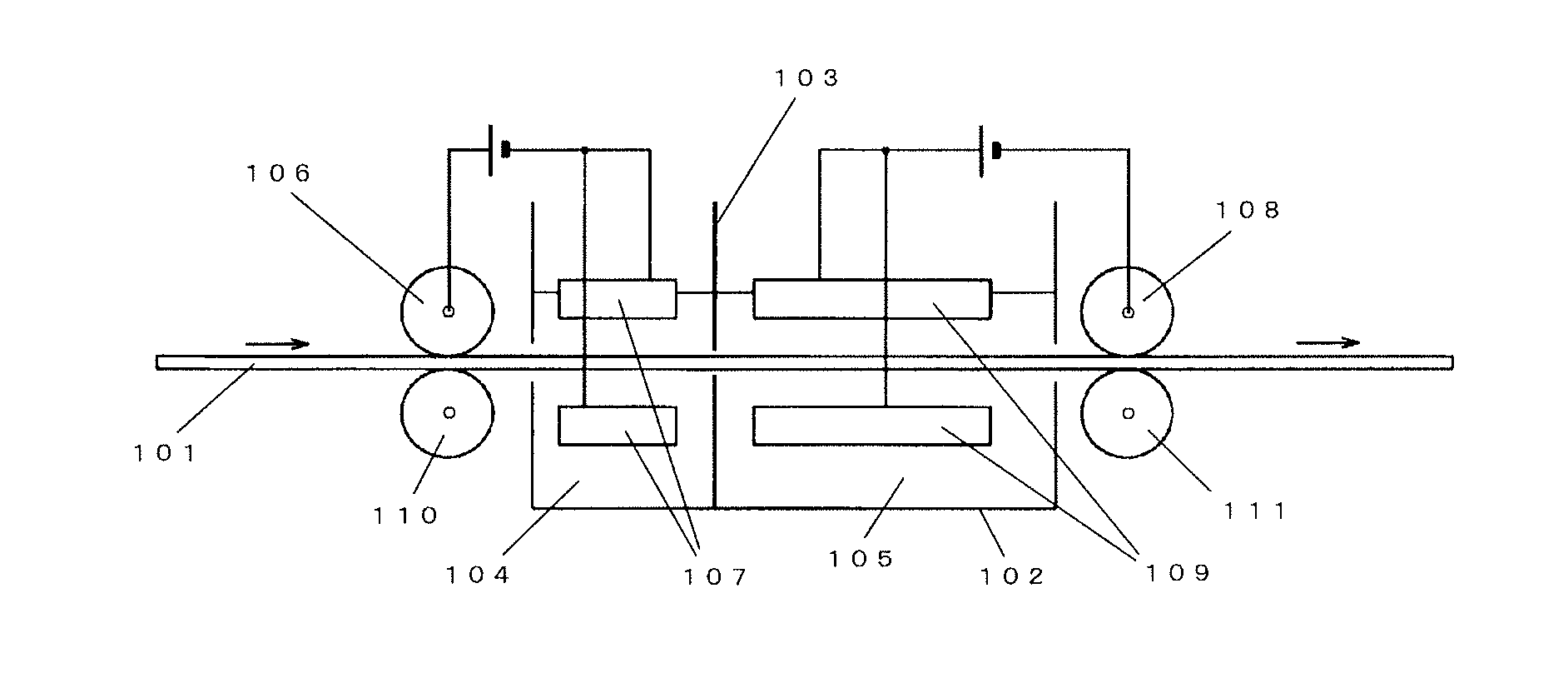
[0079]Ten aluminum apparatuses of the present invention shown in FIG. 1 were placed in series to form a film of aluminum plating on a base body.

Base Body

[0080]As the base body, a resin formed body was used that had a three-dimensional network structure having a surface on which an aluminum film was formed by the sputtering process.

[0081]As the resin formed body having a three-dimensional network structure, a foamed-urethane resin formed body having a porosity of 95%, the number of pores (the number of cells) per inch of about 50, a pore diameter of about 550 μm, a width of 500 mm, and a thickness of 1 mm was used. Conductive treatment was performed by forming an aluminum film having a coating weight of 10 g / m2 on the foamed-urethane resin formed body by the sputtering process.

[0082]It was confirmed that an aluminum oxide film of 30 nm was formed in the aluminum film on the surface of the resin formed body.

Aluminum-Plating Apparatus

[0083]Ten aluminum apparatuses of the present invent...

example 2

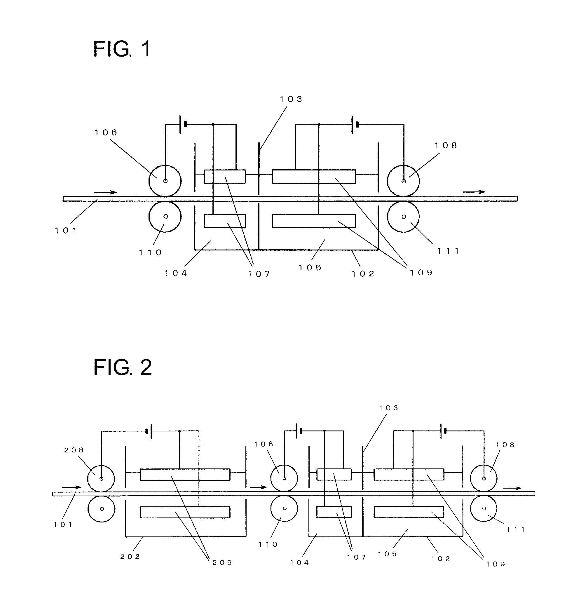
[0095]As shown in FIG. 2, a conventional aluminum-plating apparatus was placed at the most upstream side in the conveying direction for the base body. Nine aluminum apparatuses of the present invention used in Example 1 were placed in series at the downstream side of the above-described conventional aluminum-plating apparatus to form a film of aluminum plating on a base body.

Base Body

[0096]A resin formed body having the same three-dimensional network structure as that employed in Example 1 was used.

[0097]Conductive treatment of the resin formed body was carried out by coating a carbon paint as a conductive paint on the surface of a resinous porous body. The carbon paint contained 25% carbon particles, a resin binder, an introfier, and an antifoaming agent. The carbon black had a particle diameter of 0.5 μm.

Aluminum-Plating Apparatus

[0098]The conventional aluminum-plating apparatus placed at the most upstream side in the conveying direction for the base body had the same structure as...


PUM

PropertyMeasurementUnit
Structureaaaaaaaaaa
Electrical conductoraaaaaaaaaa
Electric potential / voltageaaaaaaaaaa

Abstract

The invention offers an aluminum-plating apparatus that can satisfactorily form an aluminum plating even on the surface of a base body that has a surface on which an insulating or poorly conductive metal oxide film or the like is formed. The aluminum-plating apparatus electrodeposits aluminum onto a base body by conveying the base body in a plating bath. The plating bath is divided into a first electrolysis chamber and a second electrolysis chamber by a partition plate in this order from the upstream side in the conveying direction for the base body. In the first electrolysis chamber, a negative electrode provided in the chamber is electrically connected with the base body such that the base body acts as a positive electrode. In the second electrolysis chamber, a positive electrode provided in the chamber is electrically connected with the base body such that the base body acts as a negative electrode.

Description

TECHNICAL FIELD[0001]The present invention relates to an aluminum-plating apparatus for electroplating the surface of a base body with aluminum and a method of producing an aluminum film using the foregoing apparatus.BACKGROUND ART[0002]Aluminum forms a close-knit oxide film on its surface to be passivated and thus exhibits excellent corrosion resistance. For this reason, aluminum plating is performed on the surface of a steel tape and the like to enhance the corrosion resistance.[0003]To perform aluminum plating on the surface of a steel tape, first, the steel tape is conveyed continuously into a plating bath through a conductor roll. The tape runs in a positive electrode immersed in a plating liquid in the plating bath. At this moment, the steel tape is electrically connected so as to act as a negative electrode, so that electrolysis occurs between the positive electrode and the steel tape, which is the negative electrode. As a result, aluminum is electrodeposited on the surface o...

Claims


Application Information

Patent Timeline
IPC IPC(8): C25D17/06C25D5/56C25D3/66
CPCC25D17/06C25D5/56C25D3/66C25D3/44C25D3/665C25D5/003C25D5/44C25D7/0621C25D7/0642
Inventor NISHIMURA, JUNICHIHOSOE, AKIHISAOKUNO, KAZUKIKIMURA, KOUTAROUGOTO, KENGOSAKAIDA, HIDEAKI
Owner SUMITOMO ELECTRIC IND LTD
Learn More