High efficiency beam combiner coating

a beam combiner and high-efficiency technology, applied in the field of image fusion systems, can solve the problems that the majority of available equipment is not capable of providing such data convincingly, and achieve the effect of minimizing wavelength overlap and minimizing wavelength overlap

Inactive Publication Date: 2015-07-30
EMAGIN CORP
View PDF3 Cites 111 Cited by
  • Summary
  • Abstract
  • Description
  • Claims
  • Application Information

AI Technical Summary

Benefits of technology

[0018]In accordance with an additional embodiment, a beam combiner assembly for an image fusion device using an organic-light emitting diode (OLED) display is provided. The image fusion device emits spectral bands of light, and the OLED display emits a spectrum of visible light having spectral proprieties. The assembly includes means configured to generate a combined image by combining a first image from a first imager and a second image from a second imager, the means is further configured to transmit the combined image to the OLED display. The assembly includes means for minimizing overlap of wavelengths between the bands of light emitted from the image fusion device and the OLED display.
[0019]The means for minimizing overlap of wavelengths between the bands of light emitted from the image fusion device and the OLED display is an optical coating.

Problems solved by technology

However, most of the available equipment is not capable of providing such data convincingly.

Method used


Image

  • High efficiency beam combiner coating
  • High efficiency beam combiner coating
  • High efficiency beam combiner coating

Examples


Embodiment Construction

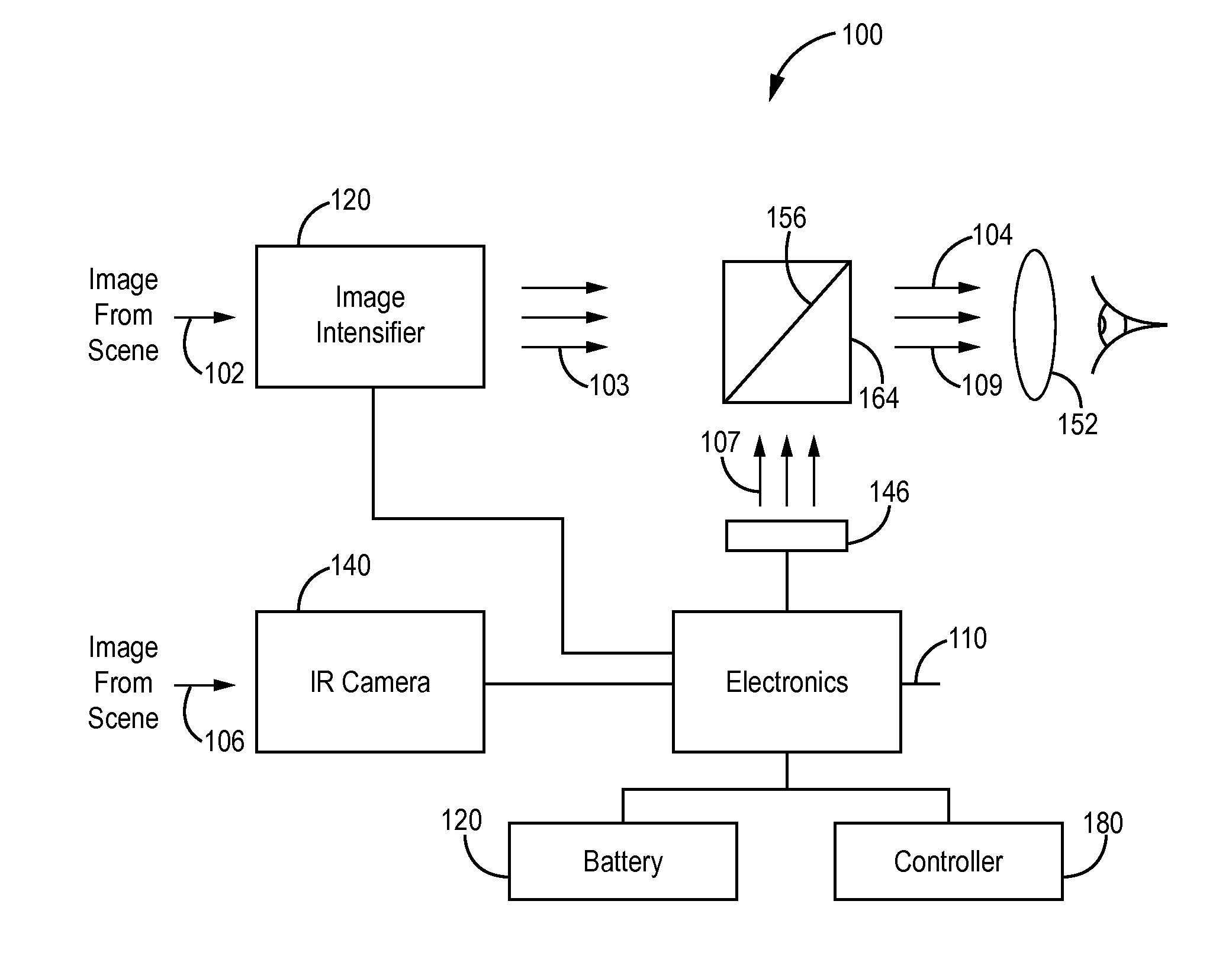
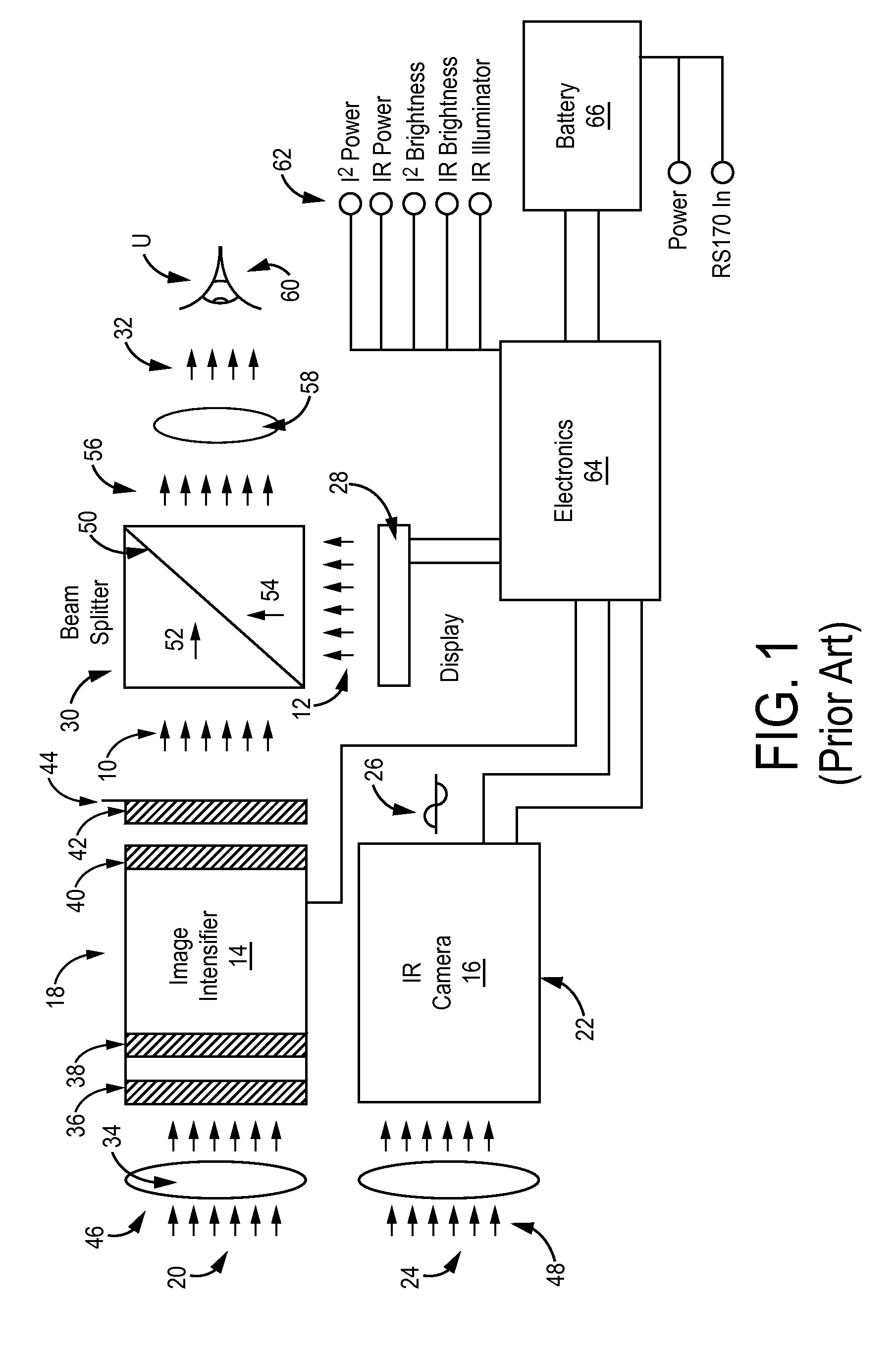
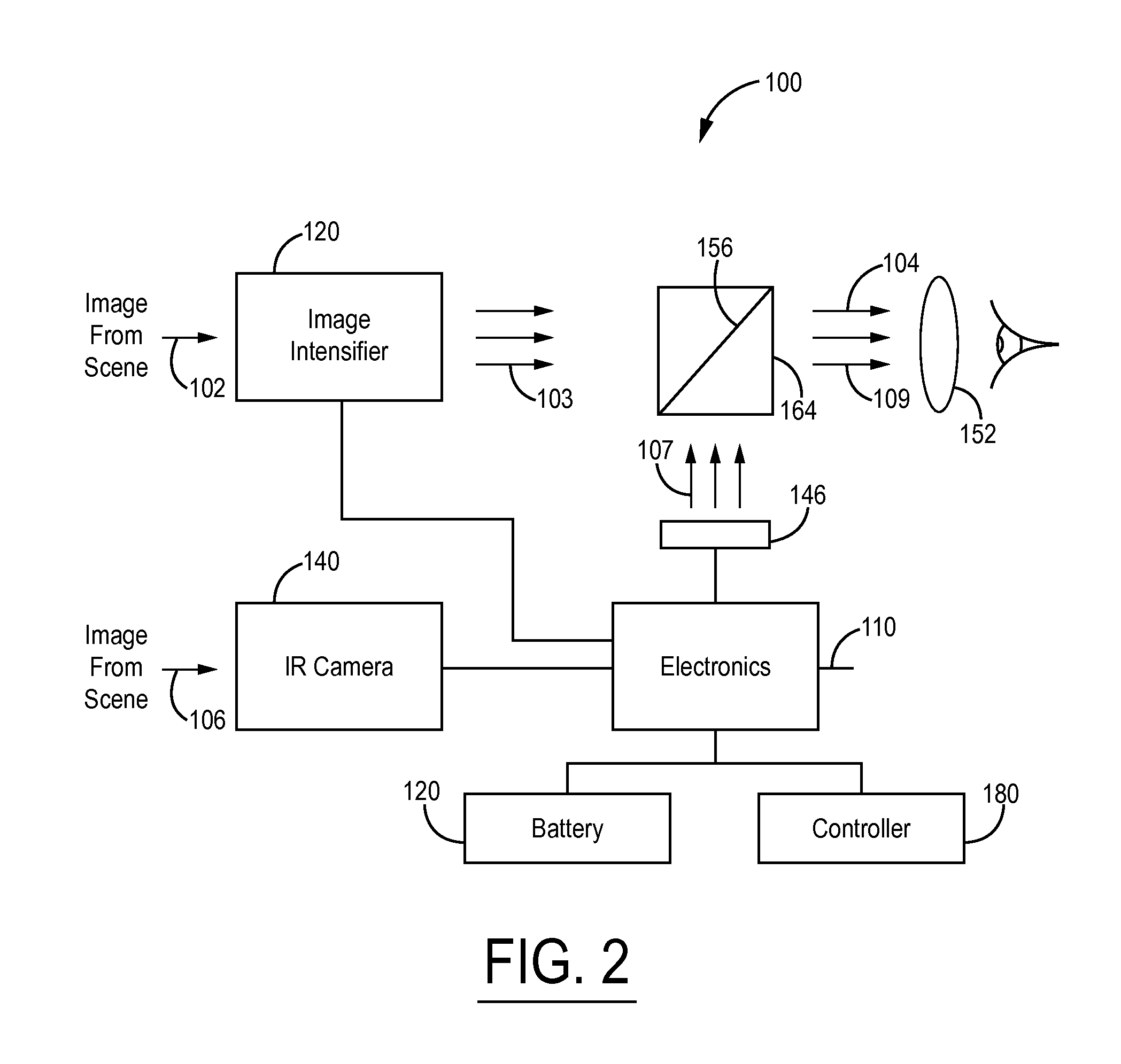
[0033]FIG. 1 illustrates the prior art, which describes a night vision system 8 or device that provides fusion of two images 12 originating from an image intensifier 14 and an infrared camera 16.

[0034]The system 8 for combining multi-spectral images of a scene includes a first channel or detector 18 for transmitting a scene image 20 in a first spectral band. A separate, second detector 22 senses the scene 22 in a second spectral band. The second detector 22 has an electronic signal image output 26 that is representative of the scene 22. A display 28 displays an image 12 in the second spectral band. A beam mixer 30 combines the image output 10 in the first spectral band with the displayed image 12, and conveys the combined multi-spectral images to an output 32 for a user U.

[0035]The image intensifier 14 provides an imager using known photo-cathode, multi-channel plate, and phosphor screen technology. Visible and near infrared light is collected by an optical element (objective) 34 an...


PUM


Abstract

A system having an improved optical coating for use in beam combiner assemblies for an image fusion device using an organic light-emitting diode (OLED) display. The system combines multi-spectral images of a scene having superior reflection of the OLED display image while incorporating high transmission of the image fusion device while allowing low power requirements on the system.

Description

CROSS-REFERENCE TO RELATED APPLICATION[0001]This application claims priority to U.S. Provisional Patent Application Ser. No. 61 / 931,971, entitled “High Efficiency Beam Combiner Coating for OLED Display Image Fusion”, filed in the United States Patent and Trademark Office on Jan. 27, 2014, the entire disclosure of which is incorporated by reference herein.BACKGROUND OF THE INVENTION[0002]1. Field of the Invention[0003]This invention relates generally to image fusion systems employing an organic light emitting diode (“OLED”) display with which to fuse images from different spectral channels, and more particularly, to a system having an improved optical coating for use in beam combiner assemblies for an image fusion device using an organic light-emitting diode (OLED) display. The system combines multi-spectral images of a scene having superior reflection of the OLED display image while incorporating high transmission of the image fusion device while allowing low power requirements on t...

Claims


Application Information

Patent Timeline
Patent Type & Authority Applications(United States)
IPC IPC(8): G09G3/32
CPCG09G2320/0238G09G3/3208G09G2340/10G02B23/12G09G2340/06
Inventor AMJAD, MALIK I.
Owner EMAGIN CORP
Why Eureka
Try Eureka