Perpendicular magnetic recording medium

Active Publication Date: 2015-07-30
FUJI ELECTRIC CO LTD
View PDF2 Cites 9 Cited by
  • Summary
  • Abstract
  • Description
  • Claims
  • Application Information

AI Technical Summary

Benefits of technology

[0022]According to the present invention, it is possible to provide a perpendicular magnetic recording medium in which magnetic crystal grains are micronized to be sufficiently ordered and separated. According to the present invention, it is possible to provide a perpendicular magnetic recording medium having a high magnetic anisotropy constant Ku. According to the present invention, it is possible to provide a perpendicular magnetic recording medium having high coercivity Hc.
[0023]Further, in the present invention, when a magnetic recording layer having magnetic crystal grains containing Mn in particular and a non-magnetic crys

Problems solved by technology

As a result, the size of state-of-the-art magnetic crystal grains approaches the physical limit called a superparamagnetic limit in which magnetization cannot be maintained stably due to the influence of ambient heat.
When a magnetic recording layer having a granular structure is formed using a conventional non-magnetic non-metallic material, the magnetic anisotropy constant and

Method used


Image

  • Perpendicular magnetic recording medium
  • Perpendicular magnetic recording medium
  • Perpendicular magnetic recording medium

Examples


example 1

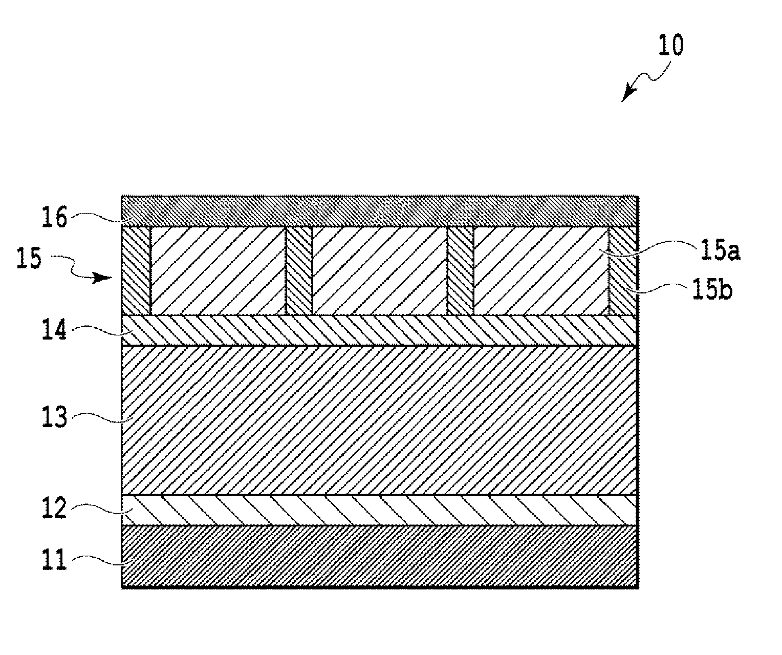
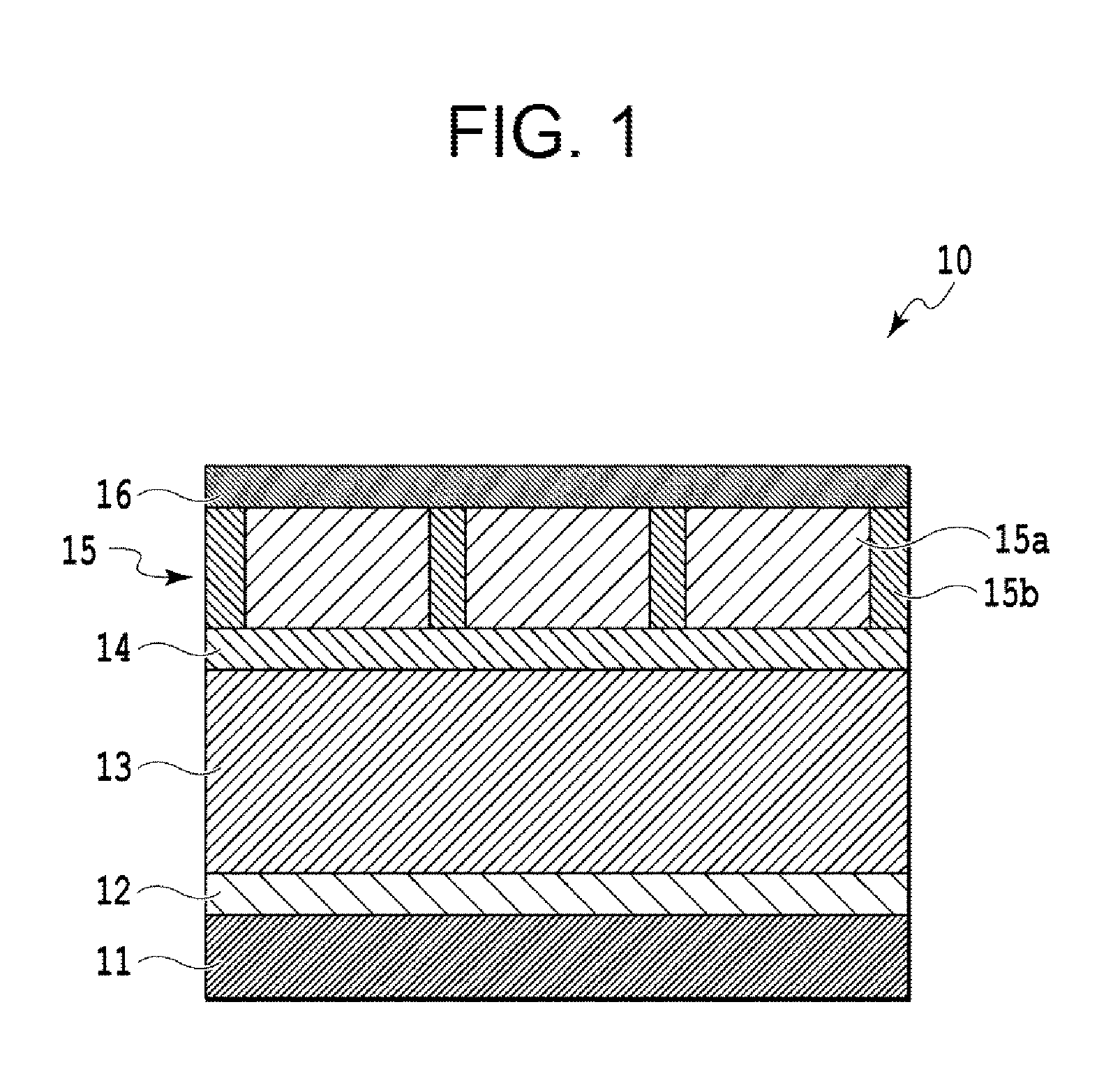
[0072]A chemically reinforced glass substrate (N-10 glass substrate manufactured by HOYA Corporation) was used as the non-magnetic substrate. The layers ranging from the Ta-based adhesion layer to the C-based protective film were formed using an in-line type film forming apparatus without exposing the layers to the atmosphere. A Ta-based adhesion layer having a thickness of 5 nm was formed in an Ar gas atmosphere according to a DC magnetron sputtering method using a pure Ta target. Further, a Cr-based underlayer having a thickness of 20 nm was formed in an Ar gas atmosphere according to a DC magnetron sputtering method using a pure Cr target. Subsequently, a MgO-based seed layer having a thickness of 5 nm was formed according to an RF sputtering method using a MgO target in a state where the substrate was heated to 300° C. When the MgO layer was formed, the pressure of the Ar gas atmosphere was 0.02 Pa and the RF power was 200 W. Subsequently, a FePt—GeO2 layer was formed as a magne...

example 2

[0073]A FePt—C layer was formed as the first magnetic recording layer in the following manner. Specifically, the substrate was heated to 450° C., and then, the FePt—C layer having a thickness of 2 nm was formed according to a DC magnetron sputtering method using a target including FePt and C. The target including FePt and C was adjusted so as to have a composition of 60 vol % of FePt and 40 vol % of C during deposition. When the FePt—C layer was formed, the pressure of the Ar gas atmosphere was 1.0 Pa and the input DC power was 25 W. Subsequently, a FePt—GeO2 layer was formed as the second magnetic recording layer in the following manner. Specifically, the substrate was heated to 450° C., and then, a FePt—GeO2 layer having a thickness of 7 nm was formed according to a DC magnetron sputtering method using a target including FePt and GeO2. The target including FePt and GeO2 was adjusted so as to have a composition of 75 vol % of FePt and 25 vol % of GeO2 during deposition. When the Fe...

example 3

[0074]Layers were formed using the same method as used in Example 2 except that the FePt—GeO2 layer of Example 2 had a thickness of 3 nm.


PUM


Abstract

A perpendicular magnetic recording medium includes a non-magnetic substrate; and a magnetic recording layer that includes magnetic crystal grains and a non-magnetic crystal grain boundary that surrounds the magnetic crystal grains, wherein the magnetic crystal grains contain an ordered alloy and the non-magnetic crystal grain boundary contains Ge oxides. The magnetic recording layer may have a granular structure. The magnetic crystal grains may be micronized to be sufficiently ordered and separated, and the perpendicular magnetic recording medium may have a high magnetic anisotropy constant Ku and high coercivity Hc.

Description

CROSS-REFERENCE TO RELATED APPLICATION(S)[0001]This non-provisional application is a continuation of and claims the benefit of the priority of Applicant's earlier filed International Application No. PCT / JP2013 / 007199 filed Dec. 6, 2013, the entire contents of which are incorporated herein by reference.BACKGROUND OF THE INVENTION[0002]1. Field of the Invention[0003]The present invention relates to a perpendicular magnetic recording medium and, more particularly, to a perpendicular magnetic recording medium that contains Ge oxides.[0004]2. Background of the Related Art[0005]Conventionally, a perpendicular magnetic recording scheme for realizing perpendicular magnetization of a surface of a magnetic recording layer (magnetization film) of a magnetic recording medium has been used as a recording scheme of magnetic recording apparatuses. A magnetic recording medium used in the perpendicular magnetic recording (hereinafter perpendicular magnetic recording medium) includes a non-magnetic s...

Claims


Application Information

Patent Timeline
IPC IPC(8): G11B5/65G11B5/66
CPCG11B5/66G11B5/65G11B5/672
Inventor ONO, TAKUYASHIMATSU, TAKEHITO
Owner FUJI ELECTRIC CO LTD
Why Eureka
Try Eureka